
Page 23 - Skilled Trades Brochure 2023 WEB
P. 23
Fundamental Fluids FM1000 Fundamental Fluids FM1000
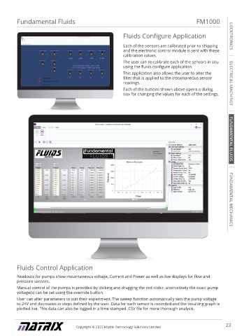
Fluids Configure Application LOCKTRONICS
Losses in Bends Module Each of the sensors are calibrated prior to shipping
and the electronic control module is sent with these
LOCKTRONICS
The losses in bends module consists of a clearly visible calibration values.
fluid path with 3 different 90° bend geometries. The user can re-calibrate each of the sensors in situ
Each of the bends have self-sealing pressure ports using the fluids configure application.
before and after each bend so the pressure drop can This application also allows the user to alter the
be measured using the multitube manometer module. filter that is applied to the instantaneous sensor
readings. ELECTRICAL MACHINES
Each of the buttons shown above opens a dialog
box for changing the values for each of the settings.
Viscosity Apparatus
ELECTRICAL MACHINES
The viscosity apparatus consists of a 100mm diameter
clear acrylic tube filled with vegetable glycerine.
This assembly is housed in a sturdy metal enclosure
which protects it whilst in storage or being transported.
It features ¼-turn valves at the top and bottom to
enable releasing and retrieving spherical samples FUNDAMENTAL FLUIDS
used in the experiment.
The experiment demonstrates Stoke’s law. Students
determine the viscosity of the glycerine by measuring
the terminal velocity of spherical samples through the
FUNDAMENTAL FLUIDS
fluid.
Centre of Pressure Module
The Centre of pressure module is used for determining
the centre of pressure of partially and fully submerged
surfaces. This experiment is carried out manually by FUNDAMENTAL MECHANICS
students who are able to take readings and plot them
within the curriculum for analysis.
FUNDAMENTAL MECHANICS
Venturi Tube Module
The Venturi tube module is used to investigate Fluids Control Application
Bernoulli’s principle.
The flow section is constricted resulting in a pressure Readouts for pumps show instantaneous voltage, Current and Power as well as live displays for flow and
pressure sensors.
drop.
Pressure ports at the widest and narrowest section Manual control of the pumps is provided by clicking and dragging the red slider, alternatively the exact pump
voltage(s) can be set using the override button
permit attaching the differential pressure sensor for
automated readings or the manometer module can be User can alter parameters to suit their experiment. The sweep function automatically sets the pump voltage
attached to enable manual readings. to 24V and decreases in steps defined by the user. Data for each sensor is recorded and the resulting graph is
plotted live. This data can also be logged in a time stamped .CSV file for more thorough analysis.
22 Copyright © 2023 Matrix Technology Solutions Limited Copyright © 2023 Matrix Technology Solutions Limited 23