Hey Benj,
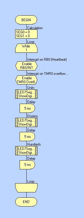
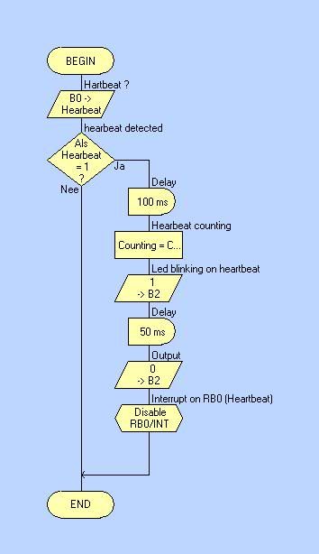
I used your idea in my code. Now we can see after 10 seconds the beats per minute on the 3 x 7segemtendisplay ( see attachment for the program).
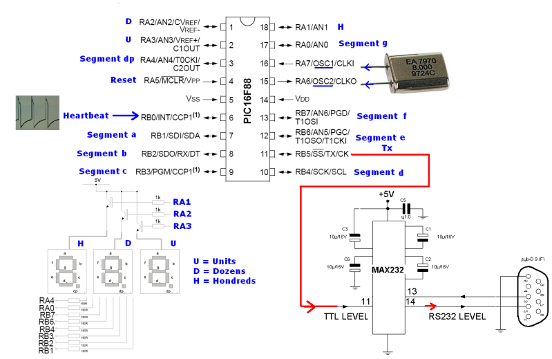
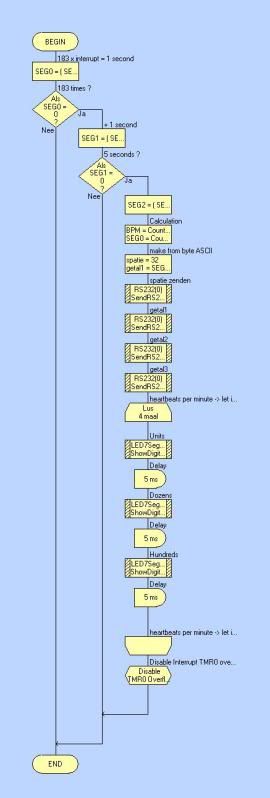
The intention is to show the beats per minute after 10 seconds on the displays for a few seconds and write this value to the computer and restart this process automatically again. So the computer gets every 10 seconds the value ( BPM). Now, we switched from chip. First we used the PIC16F84A buth now we use
the PIC16F88 because this chip has UART on board. In my code i tried to use the RS232(0) macro for sending the beats per minute to the computer. Where we monitore the average beats per minute. Buth we have problems using this macro. Can you help us out?
Thanks for the support, Benj
--------------------------------------------------------------------------------------------------------------------------------------------------------------------------------------------
Hey Keith,
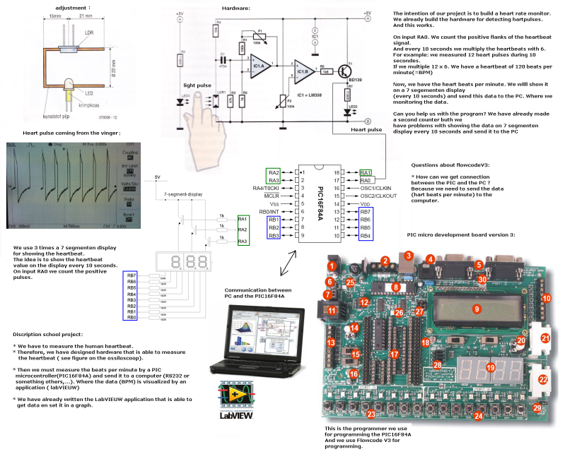
Here is a better image of the circuit for you.
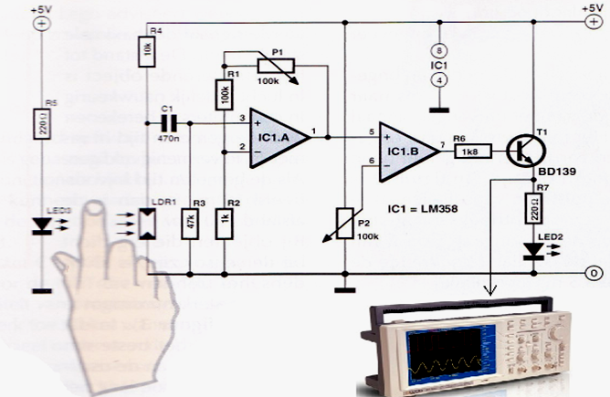
Components:
• LED3 = High intensity led, at least 1000 mcd.
• LDR1 = light dependent resistor;
• ( resistance in the dark = 1M Ohm and resistance in light = circa 300 Ohm)
• R1 = 100K Ohm
• R2 = 1K Ohm
• R3 = 47K Ohm
• R4 = 10K Ohm
• R5 = 220 Ohm
• R6 = 1K8 Ohm
• R7 = 220 Ohm
• P1 = 100K Ohm (potentiometer)
• P2 = 100 K Ohm (potentiometer)
• C1 = 470nF
• IC1 = LM358 ( comporator).
Discripton circuit:
LED3 shines through the finger on the LDR1. Each time the heart is pumping a 'wave' blood through the finger. The finger is getting darker inside so less light falls on the LDR1. This phenomenon is measurable and convertible to an electrical pulse. For each heart pulse the resistance of the LDR1 changes and the voltage on the input of comparator IC1a also changes. The reinforcement of the opamp is adjustable with potentiometer P1. The sensitivity of the circuit is adjustable with potentiometer P2.Output driver transistor T1 controls LED2 and will blink on the frequency of the heart. Remark: You must see that LRD1 only catch the light that’s comes from LED3 trough your finger and not the light from the environment.
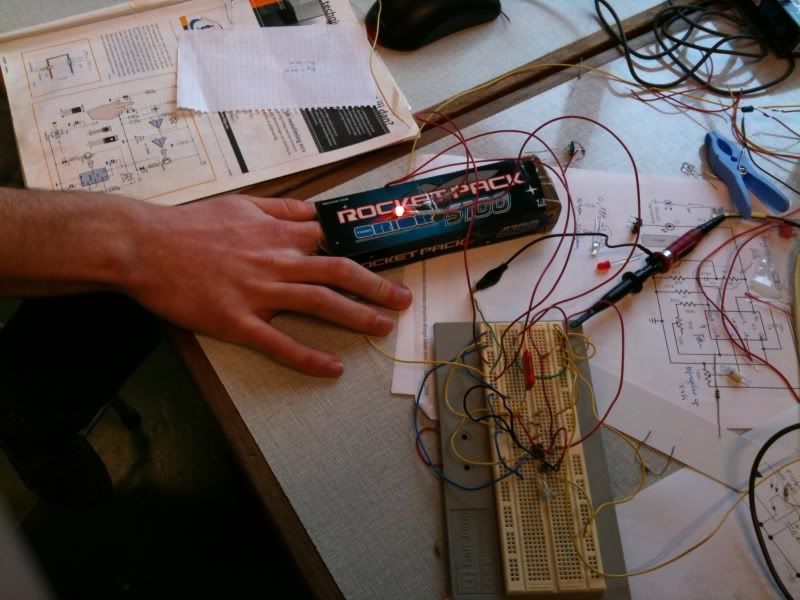
which can lead to interference. So you need to experiment with the construction of LED3 and LDR1. We used a box (see picture).
I hope i helped you with this post,
Greetz,
Dieter