
Page 45 - Aerospace Training Range Brochure 2023 WEB
P. 45
MODULE 2.0
Flowcode Embedded helps students learn to develop MODULE 2.0
complex embedded systems. It allows students to progress
MODULE 3.0
MODULE 3.0
faster and go further than other programming languages.
• Create highly functional microcontroller projects using Rpi,
Arduino, PIC, ESP, ARM and AVR processors
• Graphical programming: use flowcharts, state diagrams and data MODULE 4.0
flow techniques
• Full simulation – electrical and mechanical
MODULE 4.0
Flowcode App Developer allows students to easily develop • Hugh library of parts and subroutines
highly functional projects for Windows computers and tablets
using low cost hardware interfaces.
• Create great Windows Human Machine interfaces for control and Design MODULE 5.0
data gathering using Rpi, Arduino, PIC, ESP
MODULE 5.0
• Graphical programming: use flowcharts, state diagrams and data Design your electronic system on screen:
flow techniques • Choose a microcontroller that has the characteristics your
• Comprehensive library of dials, switches, indicators, graphs and application needs.
other components • Develop a model of the electronic system using the 2D or 3D
panels. MODULE 8.0
• Add components from the library or create your own. Link to a
General input output interface for Arduino mechanical model exported from Solidworks.
MODULE 8.0
Design • Design a program using flow chart, Blocks, Pseudo-code, C code
or state machine diagrams.
Design your electronic system on screen: • Develop a Human Machine Interface to provide a good visual test
bed. Flowcode design example MODULE 11.0
• Choose the Input Output device(s) that has the characteristics
your application needs from four types of device
MODULE 11.0
• Choose from one of our own low cost hardware interfaces or use Simulate
any third party hardware
• Add other instruments and systems that have Application Simulate your design to see how it functions:
Programming Interfaces you can work with like signal generators, • Use on-board digital switches and analogue sliders to change real
environmental chambers etc world parameters and see how your system copes.
• Drag local (USB/Bluetooth) and remote (Wi-fi/LAN/Internet) • Use the Meters, Oscilloscope, Data Recorder, Console or Graph to
hardware components onto the 2D panel verify your system’s performance.
• Add components from the library to create a distributed • Use test signal injectors to send streams of comms data in any
electronic system protocol to see how your system responds.
Control system with USB, LAN, Wi-fi and Bluetooth connection
• Design a program using flow chart, Blocks, Pseudo-code, or state • Link to Solidworks to see your 3D hardware model move on
machine diagrams screen under control of your program.
Simulation with a robot arm
Test
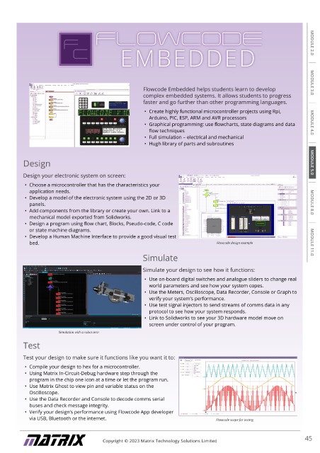
Test your design to make sure it functions like you want it to: Test
Test your design to make sure it functions like you want it to:
• Link your design to low cost local or remote hardware interfaces
• ‘Play’ the program or step through the program one command at • Compile your design to hex for a microcontroller.
a time to make sure it works • Using Matrix In-Circuit-Debug hardware step through the
• Use the on-screen instruments to see the variables in your program in the chip one icon at a time or let the program run.
system • Use Matrix Ghost to view pin and variable status on the
• Use the Data Recorder and Console to monitor your program and Oscilloscope.
see how it is working • Use the Data Recorder and Console to decode comms serial
• Use the Graph plotter to document the performance of your buses and check message integrity.
system in real time • Verify your design’s performance using Flowcode App developer
Process Control software built with App Developer
via USB, Bluetooth or the internet. Flowcode scope for testing
44 Copyright © 2023 Matrix Technology Solutions Limited Copyright © 2023 Matrix Technology Solutions Limited 45