Ghost Settings
A page detailing the various settings for Ghost.
Contents
Ghost Features
Ghost consists of the following functionality:
ICD - In Circuit Debug - Allows you to step through your program in hardware using the controls in Flowcode, Run, Pause, Stop, Step Into, Step Over, Breakpoints, Variable watching.
ICT - In Circuit Test - Allows you to monitor the signals present on the microcontroller pins.
Enabling Ghost
Ghost is controlled using three buttons on the main Flowcode tool bar. Note that these buttons only become available when Ghost enabled hardware is connected.
ICD Button
The ICD button toggles the ICD functions on and off.
When ICD mode is enabled the simulation icons turn from red to green indicating that they are now controlling the execution of the hardware rather than the simula0tion.
After enabling ICD mode you will have to re-compile the Flowcode project to your hardware to allow the ICD code to be on-board the target device.
Please note that the ICD code will consume some of the devices ROM so the program may run slower and use more memory when ICD is enabled.
ICT Button
The ICT button toggles the ICT functions on and off.
When ICT mode is enabled, pin data from the hardware will automatically start to be streamed into Flowcode and can be seen using the Data Recorder or Oscilloscope windows.
To configure the Data Recorder window you can use the Tools -> Scope Monitor component to define which pins you would like to see.
Configuration Button
The configuration button allows the ICD and ICT modes to be configured as shown below.
Ghost Configuration
The Ghost Configuration window has three tabs each of which controls a different aspect of the Ghost functionality.
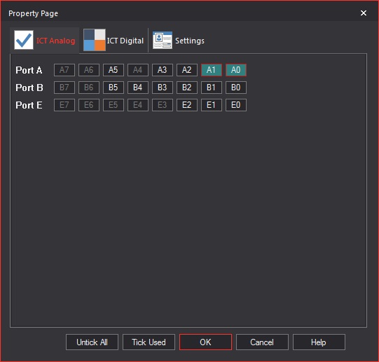
ICT Analog
The ICT Analogue window controls which of the targets analogue pins will be monitored.
The pins available will change to reflect your Flowcode target Microcontroller.
Pins marked in blue are enabled and will be recorded.
Analogue pins are sampled in sequence one after another.
If the ICT analogue sample rate is 100KHz and only one analog channel is enabled then the sample rate of that channel will be 100KHz.
If the ICT analogue sample rate is 100KHz and two analog channels are enabled then the sample rate of the channels will be 50KHz.
If the ICT analogue sample rate is 100KHz and four analog channels are enabled then the sample rate of the channels will be 25KHz.
Therefore it is recommended to only enable the analog pins you wish to monitor.
Untick All - Deselects all analog pins.
Tick Used - Scans the Flowcode program for analog pins being used and automatically enables those pins.
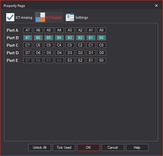
ICT Digital
The ICT Digital window controls which of the targets digital pins will be monitored.
The pins available will change to reflect your Flowcode target Microcontroller.
Pins marked in blue are enabled and will be recorded.
Digital pins are sampled together so it doesn't matter how many digital pins you have enabled. The sample rate will not be effected.
Note that ICT in digital mode will log any pin change and so if there are pins which are changing often e.g. PWM outputs then it is wise to disable the ICT monitoring for these pins unless you specifically require them. Leaving these pins enabled will consume a lot of the ICT bandwidth which will increase the data load and may eventually cause the hardware ICT buffer to run out of memory, especially at higher sample speeds.
Untick All - Deselects all digital pins.
Tick Used - Scans the Flowcode program for digital pins being used and automatically enables those pins.
Settings
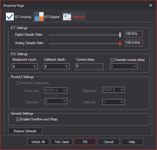
The Settings window controls various aspects of the ICD and ICT functionality.
ICT Settings: Controls the digital and analog sample rates, note that the analogue sample rate is scaled based on the digital sample rate.
ICD Settings: Controls the number of breakpoints, the maximum size of the stack and the communications time out delay.
Flowkit 2 Settings: Only configurable when you have a FlowKit 2 board connected, these control the two target pins used for ICD communications. These pins cannot be used in your program or you risk ICD communications being unreliable or unavailable.
General Settings: Enable Overflow and Wrap: This controls what happens if the ICT buffer runs out of memory.
Checked: If the ICT buffer runs out of memory then the contents of memory are wiped allowing ICT to continue, you may notice a glitch on your scope traces.
Unchecked: If the ICT buffer runs out of memory then ICT mode is automatically switched off, this guarantees that there are no glitches in the data.


