Difference between revisions of "Exercise - Dashboard Panel - Adding Objects"
From Flowcode Help
Jump to navigationJump to searchJohnVerrill (talk | contribs) |
JohnVerrill (talk | contribs) |
||
| Line 59: | Line 59: | ||
::: The 'Create a New Variable' dialogue box opens. Enter the name "input" for the new variable. | ::: The 'Create a New Variable' dialogue box opens. Enter the name "input" for the new variable. | ||
::: Leave the 'Initial value' and 'Description' boxes empty, and leave the variable type as 'byte'. | ::: Leave the 'Initial value' and 'Description' boxes empty, and leave the variable type as 'byte'. | ||
| − | ::: Click on 'OK'. [[File: | + | ::: Click on 'OK'. [[File:Gen exerciseDashPaneladdobjects headprog 01.png|400px|right]] |
::: In the 'Variable:' box in the input properties dialogue box, type the name "input". | ::: In the 'Variable:' box in the input properties dialogue box, type the name "input". | ||
::: Select PORT B as the 'Port:' and 'Input from:' 'Single Bit:' 0. | ::: Select PORT B as the 'Port:' and 'Input from:' 'Single Bit:' 0. | ||
| Line 83: | Line 83: | ||
::: Click on 'OK'. | ::: Click on 'OK'. | ||
| − | * The flowchart should resemble the one opposite. Save it as " | + | * The flowchart should resemble the one opposite. Save it as "Headlight warning". |
| − | + | ||
==What Next== | ==What Next== | ||
Now, further switches and warning LEDs can be added to the instrument panel. This process is started in the next exercise [[Exercise - Dashboard and System Panel - Controlling Multiple Objects|Controlling Multiple Objects]]. | Now, further switches and warning LEDs can be added to the instrument panel. This process is started in the next exercise [[Exercise - Dashboard and System Panel - Controlling Multiple Objects|Controlling Multiple Objects]]. | ||
Revision as of 15:52, 8 June 2013
This exercise shows how to add a labeled switch to the Dashboard Panel, and use it to control the LED on the car's instrument panel. This will represent the warning light that tells the driver that the headlights are switched on.
The advantage of this arrangement is that switch operation is unaffected when the components on the System Panel are rotated to give different views of the arrangement.
Contents
Open the Mounted LED flowchart
- Open the flowchart "System_Panel_Add_Mounted LED" which you created in Exercise - System Panel - Controlling Shapes.
- This time, set the Panel Properties to display sizes as 'Scale'.
- To do this, click on the down arrow next to 'World size' and select the 'Local scale'option.
Set up the Dashboard Panel
- Make sure that the Dashboard Panel is visible. If it is not, then click on the View menu and tick the check box next to 'Dashboard Panel'.
- Select a suitable color for the background, such as dark green (red=0, green=128, blue=0) by clicking on the 'General options' tab.30px
Add the switch
- Click on the 'Inputs' toolbox and locate the 'Toggle Metal Panel' switch.
- Click on the down arrow next to it and then on the 'Add to dashboard panel' option.
- The switch appears at the center of the Dashboard Panel.
- Click on it to select it. Its properties are shown in the Panel Properties.
- Click on the 'pin' property. A pinout of the microcontroller appears.
- Click on pin 'RB0/Int' to connect the switch to bit 0 of PORT B.
- Add a label to identify it (as there will be others!)
- To do this:
- Click on the colored rectangle at the top of the vertical toolbar on the right-hand side of the Dashboard Panel.
- Select the color black.".
- Click on the text icon, (the letter 'T') and drag it onto the Dashboard Panel.
- It may not be visible at this stage, but the Panel Properties will show it as the object called 'label', and list four properties - 'Color' 'Background', 'Font' and 'Text'.
- The default text content is 'Please Change Caption". Click on this and overwrite it with the word "main".
- In addition change :
- the background color to yellow (0x00FFFF);
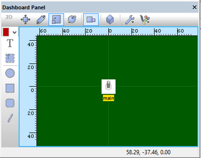
- the coordinates to 'X'=0, 'Y'=-10, 'Z'=0;
- the scale to 'Width'=5, 'Height'=5, 'Depth'=2.

- The Dashboard Panel now resembles that shown opposite:
The Flowcode flowchart
- Add an infinite loop to the flowchart, and inside it:
- Drag and drop an 'Input' icon.
- Double-click on it to configure it.
- Rename it "Check the switch".
- Click the down arrow at the end of the 'Variable:' box.
- Next click on the down arrow in front of the label 'Variables', and select the 'Add new' option.
- The 'Create a New Variable' dialogue box opens. Enter the name "input" for the new variable.
- Leave the 'Initial value' and 'Description' boxes empty, and leave the variable type as 'byte'.
- Click on 'OK'.
- In the 'Variable:' box in the input properties dialogue box, type the name "input".
- Select PORT B as the 'Port:' and 'Input from:' 'Single Bit:' 0.
- Click on 'OK'.
- Drag and drop a 'Decision' icon.
- Double-click on it to configure it.
- Rename it "Is it on?".
- In the 'If:' box, type "input=1" - using the variable 'input' you created earlier.
- Click on 'OK'.
- Drag and drop an 'Output' icon into the 'Yes' branch of the 'Decision' icon.
- Double-click on it to configure it.
- Rename it "Switch on".
- Enter the number "1" into the 'Variable or value:' box.
- Leave the other settings as 'PORTA' and 'Entire Port:'
- Click on 'OK'.
- (When Flowcode outputs the decimal value '1' to PORT A, bit 0 of that port will be set at logic 1.
- As the LED is attached to bit 0, it will switch on.)
- Drag and drop a second 'Output' icon into the 'No' branch of the 'Decision' icon.
- Double-click on it to configure it.
- Rename it "Switch off".
- Enter the number "0" into the 'Variable or value:' box.
- Select 'PORTA' and 'Entire Port'
- Click on 'OK'.
- Drag and drop an 'Input' icon.

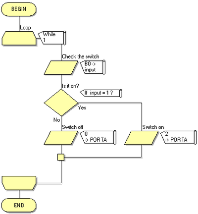
- The flowchart should resemble the one opposite. Save it as "Headlight warning".
What Next
Now, further switches and warning LEDs can be added to the instrument panel. This process is started in the next exercise Controlling Multiple Objects.