Difference between revisions of "Component: Control (DSP)"
(XML import) |
|||
| (16 intermediate revisions by 3 users not shown) | |||
| Line 4: | Line 4: | ||
|- | |- | ||
| width="20%" style="color: gray;" | Author | | width="20%" style="color: gray;" | Author | ||
| − | | | + | | Matrix Ltd |
|- | |- | ||
| width="20%" style="color: gray;" | Version | | width="20%" style="color: gray;" | Version | ||
| − | | 1.2 | + | | 1.2 (Release) |
|- | |- | ||
| width="20%" style="color: gray;" | Category | | width="20%" style="color: gray;" | Category | ||
| Line 21: | Line 21: | ||
==Examples== | ==Examples== | ||
| + | Setpoint = Value that the user wishes the system to be running at. e.g. the temperature control knob for an oven. | ||
| + | Feedback = Measurement to monitor the value we are controlling. e.g. the temperature reading inside the oven. | ||
| − | + | Control Signal = The value we want to output to the device. e.g. the signal sent to the heat element inside the oven. | |
| − | |||
| − | |||
| + | === On/Off Control === | ||
| + | Here is a basic example demonstrating on/off control. | ||
| + | {{Fcfile|On-Off Control.fcfx|On-Off Control}} | ||
If the Setpoint ADC is higher then the Feedback ADC plus the hysteresis value then the output will switch on. | If the Setpoint ADC is higher then the Feedback ADC plus the hysteresis value then the output will switch on. | ||
| Line 38: | Line 41: | ||
| − | === | + | === Simulation Models === |
| + | |||
| + | We have created demo 2nd and 3rd order macros to try and simulate the response of a 2nd and 3rd order system. These macros basically take the value of the feedback potentiometer and then try and adjust this based on how a real world system would perform with the control signal being received. These calculations are necessary for the simulation but the real hardware would do this for you based on the physical response to the control signal. | ||
| + | |||
| + | |||
| + | A second order system is a very basic real world system that can exhibit oscillations and overshoot such as a heat element. | ||
| + | |||
| + | Feedback = ((1 - SndOrd) * Feedback) + (SndOrd * ControlValue) | ||
| + | |||
| + | |||
| + | A third order system is a more complex real world system that is slightly less responsive to the control signal alone such as a motor. | ||
| + | |||
| + | SecondOrderCalc = ((1 - SndOrd) * SecondOrderCalc) + (SndOrd * ControlValue) | ||
| + | |||
| + | Feedback = ((1 - TrdOrd) * Feedback) + (TrdOrd * SecondOrderCalc) | ||
| + | |||
| + | |||
| + | SndOrd and TrdOrd are the coefficients used to tune the response of the system and should be values between 0 and 1. | ||
| − | |||
| − | |||
| + | === Proportional Control === | ||
| + | Here is a basic example demonstrating proportional control. | ||
| + | {{Fcfile|P Control.fcfx|P Control}} | ||
P control is a very basic form of control which is often used as the calculations are fairly simple. | P control is a very basic form of control which is often used as the calculations are fairly simple. | ||
| − | + | Error = (Setpoint - Feedback) | |
| + | Control Signal = P * Error | ||
| Line 54: | Line 76: | ||
As the setpoint potentiometer is altered the control signal tries to move the feedback to the correct position as fast as possible by creating a spike in the control signal which is equal to the amount of difference between the setpoint and the feedback readings multiplied by the P coefficient. | As the setpoint potentiometer is altered the control signal tries to move the feedback to the correct position as fast as possible by creating a spike in the control signal which is equal to the amount of difference between the setpoint and the feedback readings multiplied by the P coefficient. | ||
| − | |||
| − | |||
| Line 66: | Line 86: | ||
[[File:PControl2.jpg]] | [[File:PControl2.jpg]] | ||
| + | |||
| + | |||
| + | |||
| + | === Proportional & Integral Control === | ||
| + | |||
| + | Here is a basic example demonstrating proportional and integral control. | ||
| + | {{Fcfile|PI Control.fcfx|PI Control}} | ||
| + | PI control is a slightly more advanced form of control which is often used to improve on the response of the standard P controller. | ||
| + | |||
| + | Error = (Setpoint - Feedback) | ||
| + | |||
| + | Control Signal = P * (Error - Prev Error + (Error / I)) | ||
| + | |||
| + | |||
| + | One major upside of PI control is that it will work to reduce the offset between the setpoint and the actual value. One drawback of this is that a badly tuned PI controller will be very unstable due to an effect called integral wind up. | ||
| + | |||
| + | |||
| + | Here is an example of the 2nd order PI control system with a P value of 4.5 and an I value of 2.5. | ||
| + | |||
| + | [[File:PIControlT.jpg]] | ||
| + | |||
| + | |||
| + | Here is an example of the 3nd order PI control system with a P value of 4.5 and an I value of 5.0. | ||
| + | |||
| + | [[File:PIControlT2.jpg]] | ||
| + | |||
| + | |||
| + | Here is an example of the 2nd order PI control system with badly tuned P and I coefficients, notice that the control signal is permanently oscillating. | ||
| + | |||
| + | [[File:PIControlU.jpg]] | ||
| + | |||
| + | |||
| + | |||
| + | === Proportional, Integral & Derivative Control === | ||
| + | |||
| + | Here is a basic example demonstrating proportional, integral and derivative control. | ||
| + | {{Fcfile|PID Control.fcfx|PID Control}} | ||
| + | PID control is again a more advanced form of control which is often used to improve on the response of the standard PI controller. | ||
| + | |||
| + | Error = (Setpoint - Feedback) | ||
| + | |||
| + | Control Signal = P * (Error - Prev_Error + (Error / I) + D * (Error - (2 * Prev_Error) + Prev_Prev_Error)) | ||
| + | |||
| + | |||
| + | One major upside of PID control is that it will work to try and predict the system response and therefore provide the optimal control signal to allow the output to reach the setpoint as quickly as possible. One drawback of this is that a badly tuned PID controller will be very unstable due to integral wind up and derivative misguidance. | ||
| + | |||
| + | |||
| + | Here is an example of the 2nd order PID control system with a P value of 2.5, an I value of 1.5 and a D value of 0.2. | ||
| + | |||
| + | [[File:PIDControl.jpg]] | ||
| + | |||
| + | |||
| + | Here is an example of the 3nd order PID control system with a P value of 4.5, an I value of 2.5 and a D value of 0.4. | ||
| + | |||
| + | [[File:PIDControl2.jpg]] | ||
| + | |||
| + | |||
| + | Here is an example of the 2nd order PID control system with badly tuned P, I and D coefficients, notice that the control signal is permanently oscillating. | ||
| + | |||
| + | [[File:PIDControlU.jpg]] | ||
==Downloadable macro reference== | ==Downloadable macro reference== | ||
| Line 90: | Line 170: | ||
:[[Variable Types|INT]] ''Setpoint'' | :[[Variable Types|INT]] ''Setpoint'' | ||
::Value to specify the required control setpoint | ::Value to specify the required control setpoint | ||
| + | |||
| + | |||
| + | '''Return value''' | ||
| + | |||
| + | :''This call does not return a value'' | ||
| + | |||
| + | |||
| + | ===<span style="font-weight: normal;"><u><tt>ChangePID</tt></u></span>=== | ||
| + | Allows the P, I and D control parameters to be changed on the fly during a program. | ||
| + | |||
| + | '''Parameters''' | ||
| + | |||
| + | :[[Variable Types|BYTE]] ''Parameter'' | ||
| + | ::0 = P, 1 = I, 2 = D | ||
| + | |||
| + | :[[Variable Types|FLOAT]] ''Value'' | ||
| + | ::New value to assign to the P, I or D parameter | ||
| Line 136: | Line 233: | ||
<span style="font-weight: normal;"><u>Proportional</u></span> | <span style="font-weight: normal;"><u>Proportional</u></span> | ||
| − | This property is of type '' | + | This property is of type ''Floating point'' and can be referenced with the variable name ''proportional''. |
P coefficient used to perform the Proportional calculation | P coefficient used to perform the Proportional calculation | ||
| Line 142: | Line 239: | ||
<span style="font-weight: normal;"><u>Integral</u></span> | <span style="font-weight: normal;"><u>Integral</u></span> | ||
| − | This property is of type '' | + | This property is of type ''Floating point'' and can be referenced with the variable name ''integral''. |
I coefficient used to perform the Integral calculation | I coefficient used to perform the Integral calculation | ||
| Line 148: | Line 245: | ||
<span style="font-weight: normal;"><u>Derivative</u></span> | <span style="font-weight: normal;"><u>Derivative</u></span> | ||
| − | This property is of type '' | + | This property is of type ''Floating point'' and can be referenced with the variable name ''derivative''. |
D coefficient used to perform the Derivative calculation | D coefficient used to perform the Derivative calculation | ||
Latest revision as of 11:25, 13 February 2015
| Author | Matrix Ltd |
| Version | 1.2 (Release) |
| Category | DSP |
Contents
 Control component
Allows for several types of control operations to be performed on a buffer. On/Off - Standard on off control as used on most overs, toasters, irons. P/PI/PID - Mathematical control process to get to the setpoint as fast as possible, similar to the process in the human brain when steering a car.
Examples
Setpoint = Value that the user wishes the system to be running at. e.g. the temperature control knob for an oven.
Feedback = Measurement to monitor the value we are controlling. e.g. the temperature reading inside the oven.
Control Signal = The value we want to output to the device. e.g. the signal sent to the heat element inside the oven.
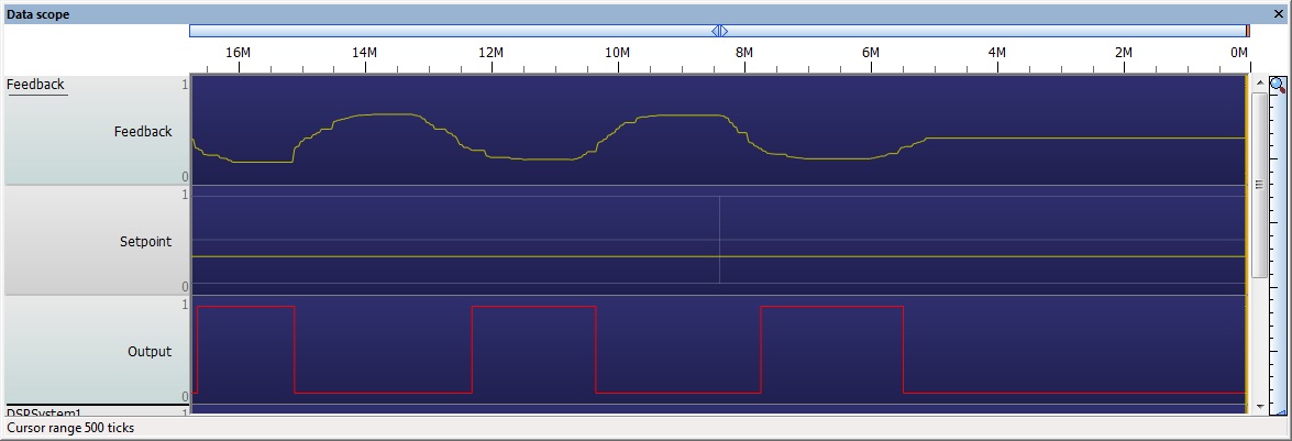
On/Off Control
Here is a basic example demonstrating on/off control.
![]() On-Off Control
If the Setpoint ADC is higher then the Feedback ADC plus the hysteresis value then the output will switch on.
On-Off Control
If the Setpoint ADC is higher then the Feedback ADC plus the hysteresis value then the output will switch on.
If the Setpoint ADC is lower then the Feedback ADC then the output will switch off.
Simulation Models
We have created demo 2nd and 3rd order macros to try and simulate the response of a 2nd and 3rd order system. These macros basically take the value of the feedback potentiometer and then try and adjust this based on how a real world system would perform with the control signal being received. These calculations are necessary for the simulation but the real hardware would do this for you based on the physical response to the control signal.
A second order system is a very basic real world system that can exhibit oscillations and overshoot such as a heat element.
Feedback = ((1 - SndOrd) * Feedback) + (SndOrd * ControlValue)
A third order system is a more complex real world system that is slightly less responsive to the control signal alone such as a motor.
SecondOrderCalc = ((1 - SndOrd) * SecondOrderCalc) + (SndOrd * ControlValue)
Feedback = ((1 - TrdOrd) * Feedback) + (TrdOrd * SecondOrderCalc)
SndOrd and TrdOrd are the coefficients used to tune the response of the system and should be values between 0 and 1.
Proportional Control
Here is a basic example demonstrating proportional control.
![]() P Control
P control is a very basic form of control which is often used as the calculations are fairly simple.
P Control
P control is a very basic form of control which is often used as the calculations are fairly simple.
Error = (Setpoint - Feedback) Control Signal = P * Error
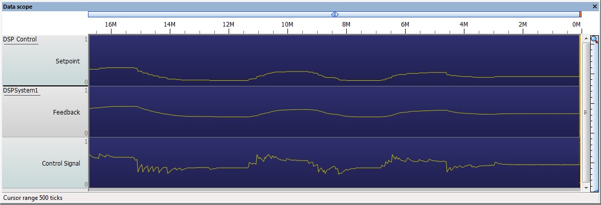
One major drawback of P control is that you will often get an offset between the Setpoint and the Feedback which cannot be removed due to the nature of the second or third order system.
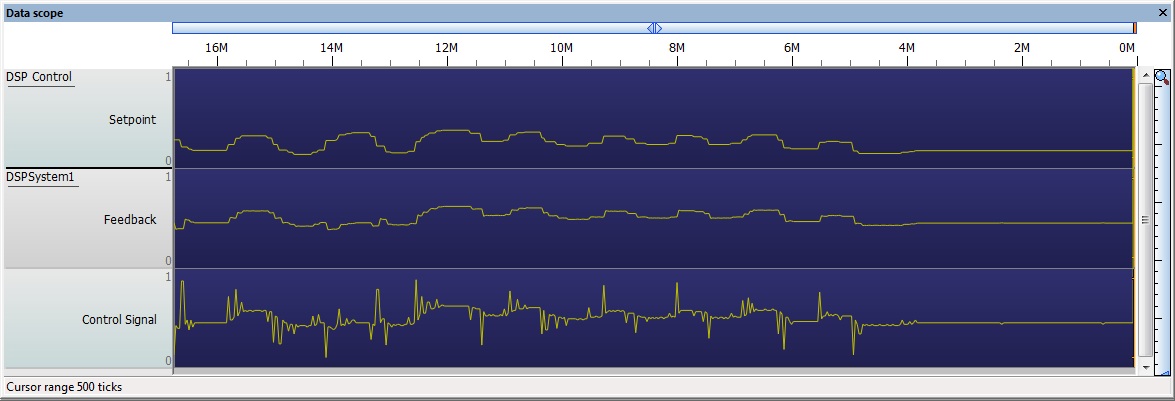
As the setpoint potentiometer is altered the control signal tries to move the feedback to the correct position as fast as possible by creating a spike in the control signal which is equal to the amount of difference between the setpoint and the feedback readings multiplied by the P coefficient.
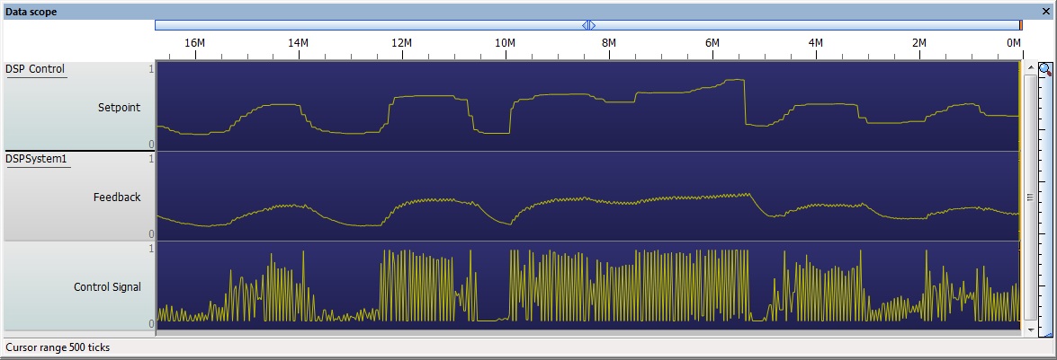
Here is an example of the 2nd order P control system with a P value of 4.5.
Here is an example of the 3nd order P control system with a P value of 4.5.
Proportional & Integral Control
Here is a basic example demonstrating proportional and integral control.
![]() PI Control
PI control is a slightly more advanced form of control which is often used to improve on the response of the standard P controller.
PI Control
PI control is a slightly more advanced form of control which is often used to improve on the response of the standard P controller.
Error = (Setpoint - Feedback)
Control Signal = P * (Error - Prev Error + (Error / I))
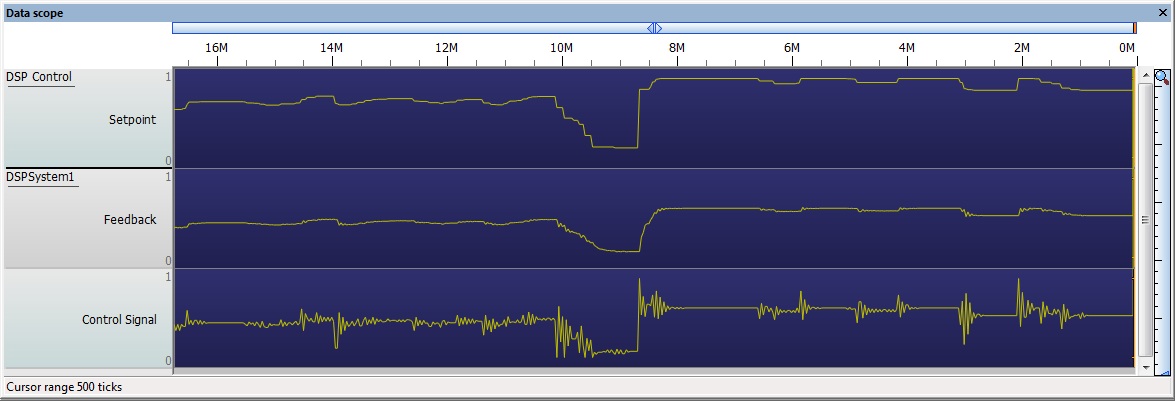
One major upside of PI control is that it will work to reduce the offset between the setpoint and the actual value. One drawback of this is that a badly tuned PI controller will be very unstable due to an effect called integral wind up.
Here is an example of the 2nd order PI control system with a P value of 4.5 and an I value of 2.5.
Here is an example of the 3nd order PI control system with a P value of 4.5 and an I value of 5.0.
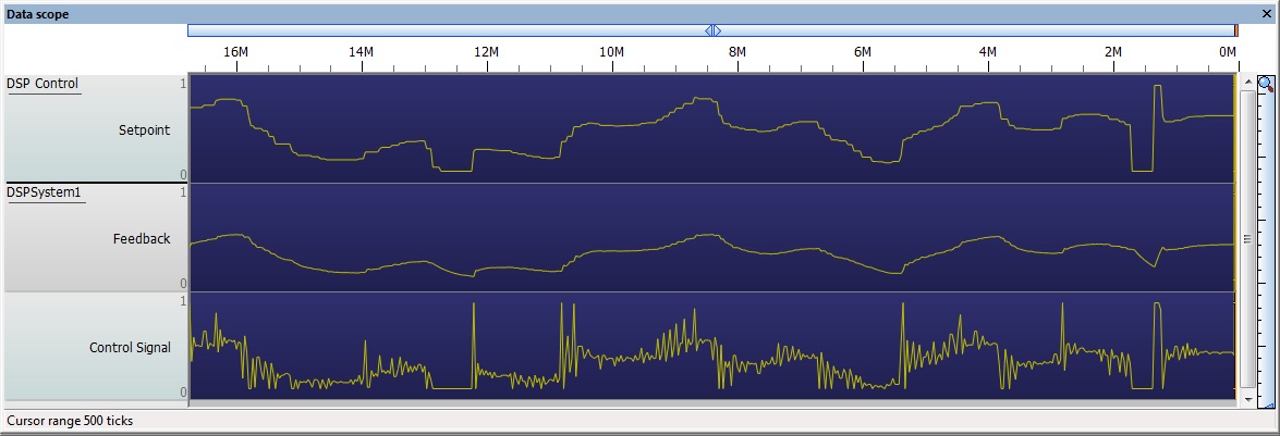
Here is an example of the 2nd order PI control system with badly tuned P and I coefficients, notice that the control signal is permanently oscillating.
Proportional, Integral & Derivative Control
Here is a basic example demonstrating proportional, integral and derivative control.
![]() PID Control
PID control is again a more advanced form of control which is often used to improve on the response of the standard PI controller.
PID Control
PID control is again a more advanced form of control which is often used to improve on the response of the standard PI controller.
Error = (Setpoint - Feedback)
Control Signal = P * (Error - Prev_Error + (Error / I) + D * (Error - (2 * Prev_Error) + Prev_Prev_Error))
One major upside of PID control is that it will work to try and predict the system response and therefore provide the optimal control signal to allow the output to reach the setpoint as quickly as possible. One drawback of this is that a badly tuned PID controller will be very unstable due to integral wind up and derivative misguidance.
Here is an example of the 2nd order PID control system with a P value of 2.5, an I value of 1.5 and a D value of 0.2.
Here is an example of the 3nd order PID control system with a P value of 4.5, an I value of 2.5 and a D value of 0.4.
Here is an example of the 2nd order PID control system with badly tuned P, I and D coefficients, notice that the control signal is permanently oscillating.
Downloadable macro reference
Process
Processes an entire buffer, either by performing the control operation to every value in the buffer or just the last value.
Parameters
- INT Setpoint
- Value to specify the required control setpoint
Return value
- This call does not return a value
ProcessTick
Processes the current value from a buffer.
Parameters
- INT Setpoint
- Value to specify the required control setpoint
Return value
- This call does not return a value
ChangePID
Allows the P, I and D control parameters to be changed on the fly during a program.
Parameters
- BYTE Parameter
- 0 = P, 1 = I, 2 = D
- FLOAT Value
- New value to assign to the P, I or D parameter
Return value
- This call does not return a value
Simulation macro reference
This component does not contain any simulation macros
Property reference
Buffer Manager
This property is of type Fixed list of ints and can be referenced with the variable name buffer_manager.
DSP buffer manager to get the buffers from
Feedback
This property is of type Fixed list of ints and can be referenced with the variable name input_a.
Feedback buffer - used to pass the feedback reading into the control algorythm.
Output
This property is of type Fixed list of ints and can be referenced with the variable name output_c.
Output buffer - used to pass the control output values from the control algorythm.
Process
This property is of type Fixed list of ints and can be referenced with the variable name style.
Selects whether to process the entire buffer or just a single value when calling the Process macro
Method
This property is of type Fixed list of ints and can be referenced with the variable name method.
Specifies which control method will be used to process the buffer data
Proportional
This property is of type Floating point and can be referenced with the variable name proportional.
P coefficient used to perform the Proportional calculation
Integral
This property is of type Floating point and can be referenced with the variable name integral.
I coefficient used to perform the Integral calculation
Derivative
This property is of type Floating point and can be referenced with the variable name derivative.
D coefficient used to perform the Derivative calculation
