Difference between revisions of "Exercise - Using Macros"
JohnVerrill (talk | contribs) |
|||
| (48 intermediate revisions by 2 users not shown) | |||
| Line 1: | Line 1: | ||
| + | <sidebar>Sidebar: Flowcode Exercises:Ex1</sidebar> | ||
Macros are sections of code that are repeated a number of times within a program.<br /> | Macros are sections of code that are repeated a number of times within a program.<br /> | ||
It is more efficient to use a macro than to create the code repeatedly every time it is needed.<br /> | It is more efficient to use a macro than to create the code repeatedly every time it is needed.<br /> | ||
| Line 4: | Line 5: | ||
This exercise shows how to use macros with a menu to create a simple LED flasher. The LED can be made to flash at different frequencies by pressing different switches. | This exercise shows how to use macros with a menu to create a simple LED flasher. The LED can be made to flash at different frequencies by pressing different switches. | ||
| − | |||
| − | |||
The first section looks at creating the core program, with the menu. The second section shows how to create the macro. | The first section looks at creating the core program, with the menu. The second section shows how to create the macro. | ||
| Line 12: | Line 11: | ||
__TOC__ | __TOC__ | ||
| − | + | ||
| − | |||
| − | |||
| − | |||
| − | |||
| − | |||
| − | |||
| − | |||
==Linking frequency and delay== | ==Linking frequency and delay== | ||
| + | [[File:Exercise_Using_Macros_LED_Flash.png|200px|right]] | ||
| + | The flowchart controlling the LED flashes is shown opposite.<br /> | ||
| + | The table that follows shows the link between length of delay in each 'Delay' icon, and the frequency of flashing. | ||
| + | The LED is switched on for one delay period, and then off for one delay period. | ||
| + | {| class="wikitable" style="text-align:center;" | ||
| − | |||
! colspan="2" | LED frequency and delay | ! colspan="2" | LED frequency and delay | ||
|- | |- | ||
| Delay in milliseconds || Frequency | | Delay in milliseconds || Frequency | ||
|- | |- | ||
| − | | 1000 ||1 | + | | 1000 ||0.5 |
| + | |- | ||
| + | | 500 ||1 | ||
| + | |||
| + | |- | ||
| + | | 250 ||2 | ||
| + | |||
| + | |- | ||
| + | | 125 ||4 | ||
|} | |} | ||
| − | + | ||
| + | |||
| + | |||
| + | |||
| + | |||
| + | |||
| + | |||
==Create the variables== | ==Create the variables== | ||
The program will use two variables, 'selection', to store the state of the switches used to select frequency, and 'delay', used to determine the frequency at which the LED flashes. | The program will use two variables, 'selection', to store the state of the switches used to select frequency, and 'delay', used to determine the frequency at which the LED flashes. | ||
| − | :* In the 'Edit' menu, | + | :* In the 'Edit' menu, select the 'Variables...' option (Edit > Variables...) to open the [[Variable Manager]] dialogue box, or use the [[Using the Project Explorer|Project Explorer]], which is the recommended method and can be enabled from the 'View' menu (View > Project Explorer). |
::* Hover just to the left of the 'Variables' label, and click on the down arrow that appears. | ::* Hover just to the left of the 'Variables' label, and click on the down arrow that appears. | ||
::* Select 'Add new' and the 'Create a New Variable' dialogue box opens. | ::* Select 'Add new' and the 'Create a New Variable' dialogue box opens. | ||
| − | ::* Name the new variable " | + | ::* Name the first new variable "selection". |
::* Leave the variable type as 'Byte'. | ::* Leave the variable type as 'Byte'. | ||
::* Click on 'OK'. | ::* Click on 'OK'. | ||
| − | ::* The dialogue box is shown opposite. | + | ::* Now do the same thing again to add the second variable "delay". |
| − | ===Set up the 'main' flowchart | + | |
| − | * Open Flowcode, and set up the new flowchart as described in [[Exercise - Creating | + | |
| + | ==Create the macro== | ||
| + | [[File:Exercise_Using_Macros_Set_Frequency_Properties.png|250px|right]] | ||
| + | * Open the 'Macro' menu on the main toolbar, and click on the 'New...' option. | ||
| + | : The 'Create a New Macro' dialogue box opens. | ||
| + | :* Name the new macro "Set_Frequency". | ||
| + | :: (Notice the underscore! | ||
| + | :: Macro names must appear to be a single word. To use more than one word, join them together with underscore characters.) | ||
| + | :* Hover to the left of the 'Parameters' label, and click on the down arrow that appears. | ||
| + | :* Click on 'Add new' and then write in the name "delay" as the variable name in the dialogue box that opens. | ||
| + | :* Leave the 'Description:' box empty, and accept the default variable type, 'Byte'. | ||
| + | :* Click on 'OK'. | ||
| + | : The dialogue box for this macro is shown opposite. | ||
| + | |||
| + | |||
| + | : Notice that this creates a new tab, called 'Set_Frequency' on the Flowcode work area. | ||
| + | [[File:Exercise_Using_Macros_Macro_Loop.png|250px|right]] | ||
| + | :* Click on this tab so that you can create the details of the macro. | ||
| + | ::* Drag and drop a 'Loop' icon between 'BEGIN' and 'END'. | ||
| + | ::* Double click on it to open its dialogue box. | ||
| + | ::* Change the 'Display name:' to "Loop ten times". | ||
| + | ::* Click on 'OK'. | ||
| + | ::* Tick the 'Loop count:' box and insert the number "10". | ||
| + | [[File:Exercise_Using_Macros_Output_Properties.png|250px|right]] | ||
| + | : The dialogue box for the 'Loop' is shown opposite. | ||
| + | |||
| + | |||
| + | ::: Inside the loop: | ||
| + | ::* Drag and drop and 'Output' icon, and double click on it. | ||
| + | :::* Change the 'Display name:' to "Switch on". | ||
| + | :::* Configure it to output value "1" to bit 0 of Port A. | ||
| + | :::* Click on 'OK'. | ||
| + | [[File:Exercise_Using_Macros_Macro_Delay.png|250px|right]] | ||
| + | : This dialogue box for the 'Output' icon is shown opposite. | ||
| + | |||
| + | |||
| + | ::* Follow this icon with a 'Delay' icon, and double click on it. | ||
| + | :::* Leave the 'Display name:' as 'Delay', and the timing units as 'milliseconds'. | ||
| + | :::* In the 'Delay value or variable:' box, type the name of the variable "delay". | ||
| + | :::* Click on 'OK'. | ||
| + | : The dialogue box for this 'Delay' is shown opposite. | ||
| + | |||
| + | |||
| + | ::* Next, place a second 'Output' icon. | ||
| + | ::: The easiest way to do this is to 'copy and paste' the first one, then select the copy and drag it into position. | ||
| + | ::* Double click on it and rename it "Switch off". | ||
| + | :::* Configure it to output value "0" to bit 0 of Port A. | ||
| + | :::* Click on 'OK'. | ||
| + | |||
| + | |||
| + | ::* Follow that with a second 'Delay' icon, configured in exactly the same way as the first. | ||
| + | ::: (Again, 'copy and paste' followed by dragging the resulting icon is the easiest way to do this.) | ||
| + | : The structure of the macro should resemble that shown below. | ||
| + | [[File:Exercise_Using_Macros_Flowchart_Progress.png|250px|center]] | ||
| + | |||
| + | ==The main sequence== | ||
| + | This part of the program uses three switches to select the frequency for the LED.<br /> | ||
| + | The flowchart sequence will be: | ||
| + | ::::* Read the state of the switches. | ||
| + | ::::* Use this state to determine the correct branch to take. | ||
| + | ::::* Set up the appropriate time delay for the chosen frequency. | ||
| + | ::::* Run the macro with that delay setting. | ||
| + | ::::* Loop back and check the switches again. | ||
| + | |||
| + | |||
| + | ==Set up the 'main' flowchart== | ||
| + | * Open Flowcode, and set up the new flowchart as described in [[Exercise - Creating a Flowchart|Creating a Flowchart]]. | ||
| + | |||
| + | * Click and drag an infinite loop, [[File:Btn Loop.gif|border]] between the 'BEGIN' and 'END' icons. | ||
| + | : Inside the loop: | ||
| + | [[File:Exercise_Using_Macros_Input_Properties.png|250px|right]] | ||
| + | :* Click and drag an 'Input' icon [[File:Btn Input.gif|border]]. | ||
| + | ::* Double click on it to open the dialogue box. | ||
| + | ::* Rename it "Read the switches" and set it up to input from the entire Port B. | ||
| + | ::* In the 'Variable:' box, type "selection" | ||
| + | ::: The three switches will be connected to bits 0, 1 and 2 of Port B. | ||
| + | ::: The state of these switches will be stored in the variable 'selection'. | ||
| + | ::* Click on 'OK'. | ||
| + | :: The input dialogue box for the 'Input' icon is shown opposite. | ||
| + | |||
| + | |||
| + | [[File:Exercise_Using_Macros_Switch_Properties.png|250px|right]] | ||
| + | :* Click and drag a 'Switch-case' icon, [[File:Btn Switch.gif|border]] after the 'Input' icon. | ||
| + | ::* Double click on it to open the dialogue box. | ||
| + | ::* Leave the 'Display name:' as 'Switch'. | ||
| + | ::* In the 'Switch:' box, type the name of the variable that will trigger the branching, "selection". | ||
| + | ::* Tick the first three 'Case:' boxes, and change the content of the third one from '3' to '4'. | ||
| + | ::* Click on 'OK'. | ||
| + | :: The 'Switch-case' dialogue box is shown opposite. | ||
| + | |||
| + | |||
| + | :* Inside each of the three branches ('=1', '=2' and '=3'), click and drag a macro icon, [[File:Btn Macro.gif|border]] and a calculation icon, [[File:Btn Calculation.gif|border]]. | ||
| + | ::* In the '=1' branch, double click on the 'Calculation' icon, and rename it "One hertz delay". | ||
| + | ::* In the 'Calculations:' box, type "delay = 500". | ||
| + | ::* In the '=2' branch, double click on the 'Calculation' icon, and rename it "Two hertz delay". | ||
| + | ::* In the 'Calculations:' box, type "delay = 250". | ||
| + | ::* In the '=4' branch, double click on the 'Calculation' icon, and rename it "Four hertz delay". | ||
| + | ::* In the 'Calculations:' box, type "delay = 125". | ||
| − | |||
| − | |||
| − | = | + | The three 'Calculation' dialogue boxes are shown below. |
| − | + | <Gallery widths=120px> | |
| − | * | + | File:Exercise_Using_Macros_Delay_Properties_01.png |
| − | :* | + | File:Exercise_Using_Macros_Delay_Properties_02.png |
| + | File:Exercise_Using_Macros_Delay_Properties_04.png | ||
| + | </gallery> | ||
| + | [[File:Exercise_Using_Macros_Flash_Macro.png|250px|right]] | ||
| + | :* Double click on each of the macro icons, in turn, and: | ||
| + | ::* change the 'Display name:' to "Flash macro"; | ||
| + | ::* click on the 'Set_Frequency' label that appears (alone) in the list of possible macros; | ||
| + | ::* type "delay" in the 'Parameters:' 'Expression' box. | ||
| + | :* Then click on 'OK'. | ||
| + | :: The resulting dialogue box is shown opposite. | ||
| + | ===Main sequence flowchart=== | ||
| + | The final flowchart for the main sequence should resemble the one shown below. | ||
| + | [[File:Exercise_Using_Macros_Main_Flowchart.png|850px|center]] | ||
| + | ==Add the electronics== | ||
| − | ===Add the | + | |
| + | ===Add the switches=== | ||
* Locate the 'Push Round Panel' switch in the 'Inputs' toolbox in the [[Tools and Views#1) Icons Toolbar|Icons toolbar]]. | * Locate the 'Push Round Panel' switch in the 'Inputs' toolbox in the [[Tools and Views#1) Icons Toolbar|Icons toolbar]]. | ||
:* Hover over the image to the left of the switch label, and click on the down-arrow that appears. | :* Hover over the image to the left of the switch label, and click on the down-arrow that appears. | ||
:* Click on the 'Add to system panel' option to select it. | :* Click on the 'Add to system panel' option to select it. | ||
| − | :* Click on the image of the switch on the System panel to select it and | + | :: An image of the push-button switch appears on the System Panel. |
| − | :* | + | :* Click on the image of the switch on the System panel to select it. |
| − | : | + | :* Use the 'Edit' menu on the main toolbar to copy and paste two more instances of this push-button switch. |
| − | :* Click on the | + | :* Click on one to select it, and use the Panel Properties to give it coordinates 'X'=-25, 'Y'=10, 'Z'=0. |
| + | :* In the same way, give the second coordinates of 'X'=0, 'Y'=10, 'Z'=0, and the third coordinates of 'X'=25, 'Y'=10, 'Z'=0. | ||
| + | :* Click on the first again, and then click on the 'Connections' property on the Panel Properties. | ||
| + | :* Use the microcontroller pinout that appears to connect the switch to Port B, bit 0. | ||
| + | :* Similarly, connect the other two switches to Port B, bit 1 and Port B, bit 2. | ||
===Add the LED=== | ===Add the LED=== | ||
| − | * Locate the 'Single LED' in the 'Outputs' toolbox in the [[Tools and Views#1) Icons Toolbar|Icons toolbar]]. | + | * Locate an LED such as the 'Single LED' or 'LED 5mm Panel' in the 'Outputs' toolbox in the [[Tools and Views#1) Icons Toolbar|Icons toolbar]]. |
:* Hover over the image to the left of the 'Single LED' label, and click on the down-arrow that appears. | :* Hover over the image to the left of the 'Single LED' label, and click on the down-arrow that appears. | ||
:* Click on the 'Add to system panel' option to select it. | :* Click on the 'Add to system panel' option to select it. | ||
| − | :* Select the LED on the System panel and drag it to a suitable position. | + | :* Select the LED on the System panel and drag it to a suitable position below the switches. |
:* Look at the Panel Properties, the 'Connection' property shows that, by default, it is connected to Port A, bit 0. | :* Look at the Panel Properties, the 'Connection' property shows that, by default, it is connected to Port A, bit 0. | ||
:: Leave it like this. | :: Leave it like this. | ||
| + | |||
| + | ===The System Panel=== | ||
| + | The System Panel should now resemble the one shown below. | ||
| + | [[File:Exercise_Using_Macros_System_Panel.png|250px|center]] | ||
| + | |||
| + | |||
| + | ==The alternative== | ||
| + | The final flowchart is much more compact because it uses a macro. The flowchart that follows does the same job, without using a macro: | ||
| + | [[File:Exercise_Using_Macros_Complete_Flowchart.png|1200px|center]] | ||
Latest revision as of 14:31, 13 March 2014
<sidebar>Sidebar: Flowcode Exercises:Ex1</sidebar>
Macros are sections of code that are repeated a number of times within a program.
It is more efficient to use a macro than to create the code repeatedly every time it is needed.
For more information about macros, see What Is a Macro?.
This exercise shows how to use macros with a menu to create a simple LED flasher. The LED can be made to flash at different frequencies by pressing different switches.
The first section looks at creating the core program, with the menu. The second section shows how to create the macro.
Contents
Linking frequency and delay
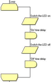
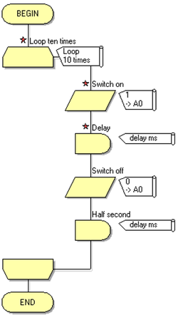
The flowchart controlling the LED flashes is shown opposite.
The table that follows shows the link between length of delay in each 'Delay' icon, and the frequency of flashing.
The LED is switched on for one delay period, and then off for one delay period.
| LED frequency and delay | |
|---|---|
| Delay in milliseconds | Frequency |
| 1000 | 0.5 |
| 500 | 1 |
| 250 | 2 |
| 125 | 4 |
Create the variables
The program will use two variables, 'selection', to store the state of the switches used to select frequency, and 'delay', used to determine the frequency at which the LED flashes.
- In the 'Edit' menu, select the 'Variables...' option (Edit > Variables...) to open the Variable Manager dialogue box, or use the Project Explorer, which is the recommended method and can be enabled from the 'View' menu (View > Project Explorer).
- Hover just to the left of the 'Variables' label, and click on the down arrow that appears.
- Select 'Add new' and the 'Create a New Variable' dialogue box opens.
- Name the first new variable "selection".
- Leave the variable type as 'Byte'.
- Click on 'OK'.
- Now do the same thing again to add the second variable "delay".
Create the macro
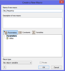
- Open the 'Macro' menu on the main toolbar, and click on the 'New...' option.
- The 'Create a New Macro' dialogue box opens.
- Name the new macro "Set_Frequency".
- (Notice the underscore!
- Macro names must appear to be a single word. To use more than one word, join them together with underscore characters.)
- Hover to the left of the 'Parameters' label, and click on the down arrow that appears.
- Click on 'Add new' and then write in the name "delay" as the variable name in the dialogue box that opens.
- Leave the 'Description:' box empty, and accept the default variable type, 'Byte'.
- Click on 'OK'.
- The dialogue box for this macro is shown opposite.
- Notice that this creates a new tab, called 'Set_Frequency' on the Flowcode work area.
- Click on this tab so that you can create the details of the macro.
- Drag and drop a 'Loop' icon between 'BEGIN' and 'END'.
- Double click on it to open its dialogue box.
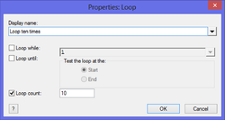
- Change the 'Display name:' to "Loop ten times".
- Click on 'OK'.
- Tick the 'Loop count:' box and insert the number "10".
- The dialogue box for the 'Loop' is shown opposite.
- Inside the loop:
- Drag and drop and 'Output' icon, and double click on it.
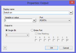
- Change the 'Display name:' to "Switch on".
- Configure it to output value "1" to bit 0 of Port A.
- Click on 'OK'.
- This dialogue box for the 'Output' icon is shown opposite.
- Follow this icon with a 'Delay' icon, and double click on it.
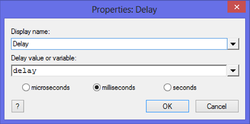
- Leave the 'Display name:' as 'Delay', and the timing units as 'milliseconds'.
- In the 'Delay value or variable:' box, type the name of the variable "delay".
- Click on 'OK'.
- The dialogue box for this 'Delay' is shown opposite.
- Next, place a second 'Output' icon.
- The easiest way to do this is to 'copy and paste' the first one, then select the copy and drag it into position.
- Double click on it and rename it "Switch off".
- Configure it to output value "0" to bit 0 of Port A.
- Click on 'OK'.
- Follow that with a second 'Delay' icon, configured in exactly the same way as the first.
- (Again, 'copy and paste' followed by dragging the resulting icon is the easiest way to do this.)
- The structure of the macro should resemble that shown below.
The main sequence
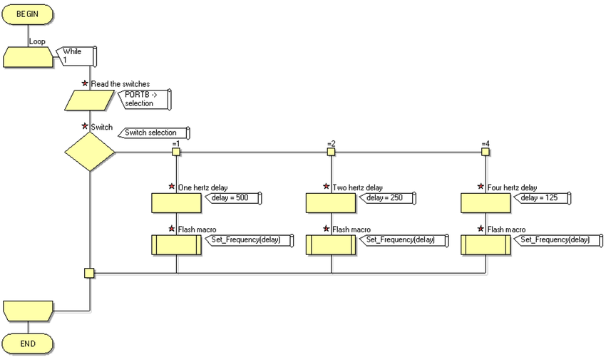
This part of the program uses three switches to select the frequency for the LED.
The flowchart sequence will be:
- Read the state of the switches.
- Use this state to determine the correct branch to take.
- Set up the appropriate time delay for the chosen frequency.
- Run the macro with that delay setting.
- Loop back and check the switches again.
Set up the 'main' flowchart
- Open Flowcode, and set up the new flowchart as described in Creating a Flowchart.
- Inside the loop:
-
- Double click on it to open the dialogue box.
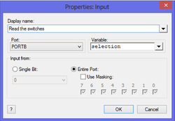
- Rename it "Read the switches" and set it up to input from the entire Port B.
- In the 'Variable:' box, type "selection"
- The three switches will be connected to bits 0, 1 and 2 of Port B.
- The state of these switches will be stored in the variable 'selection'.
- Click on 'OK'.
- The input dialogue box for the 'Input' icon is shown opposite.
-
- Double click on it to open the dialogue box.
- Leave the 'Display name:' as 'Switch'.
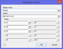
- In the 'Switch:' box, type the name of the variable that will trigger the branching, "selection".
- Tick the first three 'Case:' boxes, and change the content of the third one from '3' to '4'.
- Click on 'OK'.
- The 'Switch-case' dialogue box is shown opposite.
- Inside each of the three branches ('=1', '=2' and '=3'), click and drag a macro icon,
 and a calculation icon,
  .
.
- In the '=1' branch, double click on the 'Calculation' icon, and rename it "One hertz delay".
- In the 'Calculations:' box, type "delay = 500".
- In the '=2' branch, double click on the 'Calculation' icon, and rename it "Two hertz delay".
- In the 'Calculations:' box, type "delay = 250".
- In the '=4' branch, double click on the 'Calculation' icon, and rename it "Four hertz delay".
- In the 'Calculations:' box, type "delay = 125".
- Inside each of the three branches ('=1', '=2' and '=3'), click and drag a macro icon,
The three 'Calculation' dialogue boxes are shown below.
- Double click on each of the macro icons, in turn, and:
- change the 'Display name:' to "Flash macro";
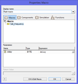
- click on the 'Set_Frequency' label that appears (alone) in the list of possible macros;
- type "delay" in the 'Parameters:' 'Expression' box.
- Then click on 'OK'.
- The resulting dialogue box is shown opposite.
Main sequence flowchart
The final flowchart for the main sequence should resemble the one shown below.
Add the electronics
Add the switches
- Locate the 'Push Round Panel' switch in the 'Inputs' toolbox in the Icons toolbar.
- Hover over the image to the left of the switch label, and click on the down-arrow that appears.
- Click on the 'Add to system panel' option to select it.
- An image of the push-button switch appears on the System Panel.
- Click on the image of the switch on the System panel to select it.
- Use the 'Edit' menu on the main toolbar to copy and paste two more instances of this push-button switch.
- Click on one to select it, and use the Panel Properties to give it coordinates 'X'=-25, 'Y'=10, 'Z'=0.
- In the same way, give the second coordinates of 'X'=0, 'Y'=10, 'Z'=0, and the third coordinates of 'X'=25, 'Y'=10, 'Z'=0.
- Click on the first again, and then click on the 'Connections' property on the Panel Properties.
- Use the microcontroller pinout that appears to connect the switch to Port B, bit 0.
- Similarly, connect the other two switches to Port B, bit 1 and Port B, bit 2.
Add the LED
- Locate an LED such as the 'Single LED' or 'LED 5mm Panel' in the 'Outputs' toolbox in the Icons toolbar.
- Hover over the image to the left of the 'Single LED' label, and click on the down-arrow that appears.
- Click on the 'Add to system panel' option to select it.
- Select the LED on the System panel and drag it to a suitable position below the switches.
- Look at the Panel Properties, the 'Connection' property shows that, by default, it is connected to Port A, bit 0.
- Leave it like this.
The System Panel
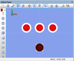
The System Panel should now resemble the one shown below.
The alternative
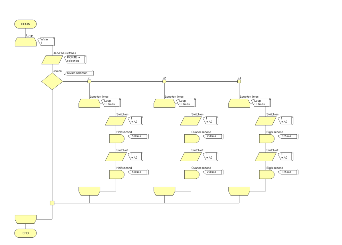
The final flowchart is much more compact because it uses a macro. The flowchart that follows does the same job, without using a macro:
