Difference between revisions of "Exercise - Configuring Icons and Variables"
| (23 intermediate revisions by 3 users not shown) | |||
| Line 1: | Line 1: | ||
| + | <sidebar>Sidebar: Flowcode Exercises:Ex1</sidebar> | ||
| + | This exercise assumes that you have already built the Flowcode flowchart described in the exercise [[Exercise - Creating a Flowchart|Creating a Flowchart]].<br /> | ||
| + | To set up and program the flowchart you must configure the icons and variables to create an effective and functioning process.<br /> | ||
| + | This will prepare the program to interact with components connected to the specific ports. | ||
| + | |||
| + | |||
| + | __TOC__ | ||
| + | |||
| + | |||
| + | ==Load the Flowcode flowchart== | ||
| + | * Open the flowchart, called 'Lamp1.fcf' which you created in the exercise [[Exercise - Creating a Flowchart|Creating a Flowchart]]. | ||
| + | :(For help with this, see the article [[Opening an Existing Flowchart]]) | ||
| + | : The System Panel and Panel Properties should be visible. If not, use the [[View]] menu to select them. | ||
| + | |||
| + | |||
| + | ==Program the sequence== | ||
| + | |||
| + | Now that the flowchart icons are correctly set up, we need to program them to carry out the following process: | ||
| + | :Check if the switch is pressed. | ||
| + | ::If it isn't, go back to the beginning. | ||
| + | ::If it is: | ||
| + | :::Switch on the lamp; | ||
| + | :::Wait for 10 seconds; | ||
| + | :::Switch off the lamp; | ||
| + | :::Go back to the beginning. | ||
| + | |||
| + | It takes such a short time for the microcontroller to carry this out, that we don't need to worry whether the switch latches on or not. | ||
| + | |||
| + | |||
==Program the input== | ==Program the input== | ||
:* Double click on the [[Input Icon Properties|Input icon]]. | :* Double click on the [[Input Icon Properties|Input icon]]. | ||
:: This opens the 'Properties: Input' dialogue box, allowing you to configure the way the program treats information from the switch. | :: This opens the 'Properties: Input' dialogue box, allowing you to configure the way the program treats information from the switch. | ||
:: This information will be contained in a variable called 'switch'. | :: This information will be contained in a variable called 'switch'. | ||
| + | |||
::* Click on the down arrow at the right-hand end of the 'Variable:' box to open the variables dialogue box. | ::* Click on the down arrow at the right-hand end of the 'Variable:' box to open the variables dialogue box. | ||
::* Hover to the left of the 'Variables' label and click on the down arrow that appears. | ::* Hover to the left of the 'Variables' label and click on the down arrow that appears. | ||
::* Click on the 'Add new' option to open the 'Create a New Variable' dialogue box. | ::* Click on the 'Add new' option to open the 'Create a New Variable' dialogue box. | ||
| + | |||
::* [[Creating Variables|Create a new variable]] named "switch" with initial value "0" and description "Copies the state of the switch" | ::* [[Creating Variables|Create a new variable]] named "switch" with initial value "0" and description "Copies the state of the switch" | ||
::* Leave the 'Variable type:' as 'Byte'. | ::* Leave the 'Variable type:' as 'Byte'. | ||
::: (For more information about variables, see [[Creating Variables]] and [[Variable Types]]. | ::: (For more information about variables, see [[Creating Variables]] and [[Variable Types]]. | ||
::: (The resulting dialogue box is shown opposite.) | ::: (The resulting dialogue box is shown opposite.) | ||
| − | [[File: | + | [[File:Exercise_Configuring_Icons_and_Variables_Input_Properties.png|250px|right]] |
| + | |||
:* Finish configuring the input properties as follows: | :* Finish configuring the input properties as follows: | ||
| Line 19: | Line 51: | ||
::: (The resulting dialogue box is shown opposite.) | ::: (The resulting dialogue box is shown opposite.) | ||
| − | [[File: | + | [[File:Exercise_Configuring_Icons_and_Variables_New_Variable.png|250px|right]] |
: Set up like this, the program monitors the state of the switch, which will be connected to bit 0 of Port A of the microcontroller. | : Set up like this, the program monitors the state of the switch, which will be connected to bit 0 of Port A of the microcontroller. | ||
: When the program looks at the input switch if it is pressed, the variable 'switch' contains logic 1. If unpressed, it contains logic 0. | : When the program looks at the input switch if it is pressed, the variable 'switch' contains logic 1. If unpressed, it contains logic 0. | ||
| + | |||
==Check the Switch== | ==Check the Switch== | ||
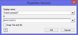
| − | :* Double click on the [[Decision Icon Properties|Decision icon]] to open the configuration dialogue box, and then: [[File: | + | :* Double click on the [[Decision Icon Properties|Decision icon]] to open the configuration dialogue box, and then: [[File:Exercise_Configuring_Icons_and_Variables_Decision_Properties.png|250px|right]] |
::* Rename it "Switch pressed?". | ::* Rename it "Switch pressed?". | ||
::* In the 'If:' box, type "switch=1". | ::* In the 'If:' box, type "switch=1". | ||
| Line 35: | Line 68: | ||
: In this case, it depends on whether or not the variable 'switch' = 1. | : In this case, it depends on whether or not the variable 'switch' = 1. | ||
: If it is, the program follows the 'Yes' route. If not, it follows the 'No' route. | : If it is, the program follows the 'Yes' route. If not, it follows the 'No' route. | ||
| + | |||
==Control the Lamp== | ==Control the Lamp== | ||
: The 'No' branch is easy to set up. All we want is that the program returns to the beginning (taken care of by the 'Loop' icon.) | : The 'No' branch is easy to set up. All we want is that the program returns to the beginning (taken care of by the 'Loop' icon.) | ||
: No further configuration is needed. | : No further configuration is needed. | ||
| − | [[File: | + | [[File:Exercise_Configuring_Icons_and_Variables_Output_Properties_01.png|250px|right]] |
| − | :* Double click the | + | :* Double click the [[Output Icon Properties|Output icon]] to open the configuration dialogue box, and then: |
::* Change the 'Display name:' to "Switch on". | ::* Change the 'Display name:' to "Switch on". | ||
::* In the 'Variable or value:' box, type value "1". | ::* In the 'Variable or value:' box, type value "1". | ||
| Line 48: | Line 82: | ||
::* Click on 'OK'. | ::* Click on 'OK'. | ||
::: (The resulting dialogue box is shown opposite.) | ::: (The resulting dialogue box is shown opposite.) | ||
| − | |||
: The effect of this icon is to send a logic 1 signal (high voltage) to the lamp, connected to Port B, bit 0 of the microcontroller. | : The effect of this icon is to send a logic 1 signal (high voltage) to the lamp, connected to Port B, bit 0 of the microcontroller. | ||
: This turns on the lamp. | : This turns on the lamp. | ||
| + | |||
| + | |||
: Now, we tackle the requirement that it stays on for ten seconds and then goes off. | : Now, we tackle the requirement that it stays on for ten seconds and then goes off. | ||
| − | [[File: | + | [[File:Exercise_Configuring_Icons_and_Variables_Delay_Properties.png|250px|right]] |
| − | * Drag and drop a | + | * Drag and drop a [[Delay Icon Properties|Delay icon]] after the 'Output' icon. |
:* Double click on it to open the configuration dialogue box, and then: | :* Double click on it to open the configuration dialogue box, and then: | ||
::* Change the 'Display name:' to "For 10 seconds". | ::* Change the 'Display name:' to "For 10 seconds". | ||
| Line 60: | Line 95: | ||
::* Change the unit to 'seconds'. | ::* Change the unit to 'seconds'. | ||
::* Click on 'OK'. | ::* Click on 'OK'. | ||
| − | ::: ( | + | ::: (The resulting dialogue box is shown opposite.) |
| − | [[File: | + | [[File:Exercise_Configuring_Icons_and_Variables_Output_Properties_02.png|250px|right]] |
: Finally, we need to turn off the lamp, after the ten second delay. | : Finally, we need to turn off the lamp, after the ten second delay. | ||
* Double click on the second 'Output' icon to allow you to configure it. | * Double click on the second 'Output' icon to allow you to configure it. | ||
| − | :* | + | :* Rename it "Switch off", and configure it to deliver value "0" to single bit 0 of Port B. |
| − | : The resulting dialogue box is shown opposite. | + | :: (The resulting dialogue box is shown opposite.) |
| + | |||
| Line 73: | Line 109: | ||
| − | ==What next== | + | ==Download the exercise== |
| + | You can download the file created by this exercise and open it in Flowcode to identify errors in your program/file or you could also download the file to skip to the next exercise. | ||
| + | |||
| + | *To download the file, click on the link below and then either: | ||
| + | :*Click on the file name. | ||
| + | :*Right click the file name and select 'Save link as...' or 'Save target as...' (depending on your browser). | ||
| + | |||
| + | :::{{Fcfile|Exercise - Configuring Icons and Variables.fcfx|Exercise - Configuring Icons and Variables}} | ||
| + | |||
| + | |||
| + | ==What next?== | ||
The next step is to add the switch and lamp to the flowchart. This is covered in the exercise [[Exercise - Adding Devices to a Program|Adding Devices to a Program]]. | The next step is to add the switch and lamp to the flowchart. This is covered in the exercise [[Exercise - Adding Devices to a Program|Adding Devices to a Program]]. | ||
Latest revision as of 14:27, 13 March 2014
<sidebar>Sidebar: Flowcode Exercises:Ex1</sidebar>
This exercise assumes that you have already built the Flowcode flowchart described in the exercise Creating a Flowchart.
To set up and program the flowchart you must configure the icons and variables to create an effective and functioning process.
This will prepare the program to interact with components connected to the specific ports.
Contents
Load the Flowcode flowchart
- Open the flowchart, called 'Lamp1.fcf' which you created in the exercise Creating a Flowchart.
- (For help with this, see the article Opening an Existing Flowchart)
- The System Panel and Panel Properties should be visible. If not, use the View menu to select them.
Program the sequence
Now that the flowchart icons are correctly set up, we need to program them to carry out the following process:
- Check if the switch is pressed.
- If it isn't, go back to the beginning.
- If it is:
- Switch on the lamp;
- Wait for 10 seconds;
- Switch off the lamp;
- Go back to the beginning.
It takes such a short time for the microcontroller to carry this out, that we don't need to worry whether the switch latches on or not.
Program the input
- Double click on the Input icon.
- This opens the 'Properties: Input' dialogue box, allowing you to configure the way the program treats information from the switch.
- This information will be contained in a variable called 'switch'.
- Click on the down arrow at the right-hand end of the 'Variable:' box to open the variables dialogue box.
- Hover to the left of the 'Variables' label and click on the down arrow that appears.
- Click on the 'Add new' option to open the 'Create a New Variable' dialogue box.
- Create a new variable named "switch" with initial value "0" and description "Copies the state of the switch"
- Leave the 'Variable type:' as 'Byte'.
- (For more information about variables, see Creating Variables and Variable Types.
- (The resulting dialogue box is shown opposite.)
- Finish configuring the input properties as follows:
- Change the 'Display name:' to "Read the switch".
- In the 'Variable:' box, type the name of the variable you created "switch".
- Leave the 'Port:' as PORT A.
- Select to 'Input from:' 'Single Bit' and choose bit 0.
- (The resulting dialogue box is shown opposite.)
- Set up like this, the program monitors the state of the switch, which will be connected to bit 0 of Port A of the microcontroller.
- When the program looks at the input switch if it is pressed, the variable 'switch' contains logic 1. If unpressed, it contains logic 0.
Check the Switch
- Double click on the Decision icon to open the configuration dialogue box, and then:
- Rename it "Switch pressed?".
- In the 'If:' box, type "switch=1".
- Leave the 'Swap Yes and No' box unchecked.
- Click on 'OK'.
- Double click on the Decision icon to open the configuration dialogue box, and then:
- This will cause the program to perform what is known as a conditional branch.
- The subsequent course of the program depends on the outcome of the condition specified in the 'Decision' icon.
- In this case, it depends on whether or not the variable 'switch' = 1.
- If it is, the program follows the 'Yes' route. If not, it follows the 'No' route.
Control the Lamp
- The 'No' branch is easy to set up. All we want is that the program returns to the beginning (taken care of by the 'Loop' icon.)
- No further configuration is needed.
- Double click the Output icon to open the configuration dialogue box, and then:
- Change the 'Display name:' to "Switch on".
- In the 'Variable or value:' box, type value "1".
- Change the 'Port:' to PORT B.
- Select to 'Output to: 'Single Bit' and choose bit 0.
- Click on 'OK'.
- (The resulting dialogue box is shown opposite.)
- The effect of this icon is to send a logic 1 signal (high voltage) to the lamp, connected to Port B, bit 0 of the microcontroller.
- This turns on the lamp.
- Now, we tackle the requirement that it stays on for ten seconds and then goes off.
- Drag and drop a Delay icon after the 'Output' icon.
- Double click on it to open the configuration dialogue box, and then:
- Change the 'Display name:' to "For 10 seconds".
- Change the 'Delay value:' to '10'.
- Change the unit to 'seconds'.
- Click on 'OK'.
- (The resulting dialogue box is shown opposite.)
- Finally, we need to turn off the lamp, after the ten second delay.
- Double click on the second 'Output' icon to allow you to configure it.
- Rename it "Switch off", and configure it to deliver value "0" to single bit 0 of Port B.
- (The resulting dialogue box is shown opposite.)
You should now save the flowchart as "Lamp1.fcf", and close Flowcode.
Download the exercise
You can download the file created by this exercise and open it in Flowcode to identify errors in your program/file or you could also download the file to skip to the next exercise.
- To download the file, click on the link below and then either:
- Click on the file name.
- Right click the file name and select 'Save link as...' or 'Save target as...' (depending on your browser).
Exercise - Configuring Icons and Variables
What next?
The next step is to add the switch and lamp to the flowchart. This is covered in the exercise Adding Devices to a Program.