Difference between revisions of "Exercise - Create an LED Component"
| Line 112: | Line 112: | ||
::* Drag a [[calculation]] icon into the macro. | ::* Drag a [[calculation]] icon into the macro. | ||
| − | ::* Double-click on it and re-name it " | + | ::* Double-click on it and re-name it "Reset pin". |
::* In the calculation area, type "pin=0", and click 'OK' | ::* In the calculation area, type "pin=0", and click 'OK' | ||
Revision as of 21:37, 21 May 2013

Contents
Creating a graphic
- Open a new Flowcode flowchart.
- Make sure that the System Panel and Properties Panel are visible.
- If they are not, then select them in the View Menu.
- Click on the hemisphere shape in the Shapes menu and drag one onto the Systems Panel.
- The blue dotted square around it shows that this object is currently selected.
- Change the name of the component to 'oneLED'.
- To do this:
- Find the 'handle' of the component at the top of the Panel Properties.
- Click on the name 'shape' (the default name).
- Change it to 'oneLED'.
Adding properties
- Next, add two properties to the LED. The first allocates a color. The second sets up a connection from the LED to the microcontroller.
- First add a default color to the component, using a new property called 'color'.
- To do this:
- De-select the hemisphere by clicking anywhere outside it in the Systems Panel.
- Hover over the icon to the right of the 'Properties' label.
- Click on the down-arrow that appears.
- Click on 'Add new'.
- In the 'Cosmetic name' box type "LEDcolor".
- Select 'Color picker' for the 'Property type'.
- Type "color" for the 'Property variable' name.
- In the same way, then add another new property to specify the default connection. Give it a Cosmetic name "Connection", with Property type 'Single digital pin' and a Property variable name "pin".
- Finally, configure these properties. To do this:
- Click on the color shown for the 'color' property.
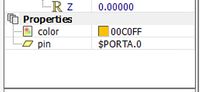
- Select a color from the color chart that appears.
- Click on the word 'Unconnected', alongside the 'pin' property.
- Select an appropriate pin, such as RA0, from the chip pin layout.
- Click on the color shown for the 'color' property.

Reacting when the pin changes state

First, create a 'PinChange' macro. The Property change event is triggered when any property you have added to your component changes.
- Open the Project Explorer from the View menu.
- Double-click on the item 'Connection -> PinChange'. The 'Add event' dialogue box opens.
- Hover over the icon to the left of the 'Macro' label. A drop-down arrow appears.
- Click on the arrow and select the option 'Add new'. The 'Edit Macro Details' dialogue box opens.
- Change the name of the macro to 'PinChange'.
- Click on 'OK'.
Next, set up the 'PinChange' macro.
- Select 'Show as Flowchart' from the 'Macro' menu, and choose the 'PinChange' macro.
Add the following details:
- Add a Decision icon to the PinChange, rename it "Pin state", and set the condition as 'If pin = 1'.
- Drag a Panel command into the 'No' branch. Configure it as follows:
- Rename it "Switch off".
- Click on the 'Functions' label.
- Expand the 'Component' and then the 'Property' sections.
- Click on the SetValue command, and complete it by adding "oneLED" as the Handle, "color" (including the quotes) as the Property and 0 (zero) as the Value. Then click on 'OK'.
- Click on the Panel command and copy and paste it into the 'Yes' branch.
- Change the configuration as follows:
- Rename it "Switch on".
- Change the Value to "color".
- Then click on 'OK'.
The flowchart now resembles that shown below.
Updating the LED
When the state of the LED pin changes, you want the color of the LED to change too. This is done through the 'Component Property' macro. This will re-use the code already created in the PinChange macro.
- Open the Project explorer as before.
- Click on the 'Functions' label.
- Expand the 'Component' section.
- Double-click on the 'Property' command to open the 'Add event' dialogue box.
- Click on the PinChange macro (to re-use it,) and then click on 'OK'.
Adding an interface
A component is not much use if no one can interact with it. What is needed is to create two macros, LEDon and LEDoff, which set and reset the state of the pin. This will become the public interface of the component.
- Click on Macro in the top toolbar, and select the 'New' option. This opens the 'Create a New Macro' dialogue box.
- Name the new macro "LEDoff", and click on 'OK'. A new tab is created on the Flowchart workspace.
- Set it up as follows:
- Drag a calculation icon into the macro.
- Double-click on it and re-name it "Reset pin".
- In the calculation area, type "pin=0", and click 'OK'
- Create the second macro in the same way. This one is called LEDon. It contains a calculation icon, called "Set pin" and the calculation "pin=1".
Declaring the interface
Flowcode needs to know what you intend to do with your macros. Are they private, for your own use, or public, so users of the component can access them?
Ensure nothing is selected on the panel. In the Properties Panel select the Interface Manager. Select each macro, LEDOn and LEDOff, in turn and declare each as a component macro. This tells Flowcode that the macro should appear in the list of component macros for the component once it is exported.
Next step
The next stage of component creation is to export the component.