Hello All,
I am working with an 18F14K50. A portion of my program is intended to detect the minimum 10 bit PWM duty cycle required to initiate a position change. I am first reading the pot with the PWM disabled, then continuously re-reading as the PWM is gradually increased. What I have noticed is that if my target is less than .03 to .04V greater than the initial reading, the loop ends on the first pass. There is actually a fair bit of movement required in order to see this much change in the pot output. i.e. the first loop read is already greater than the initial read by at least .02V A meter connected to the circuit does not show any change. I see the same behaviour if I read the ADC as int.
I have attached a short example of what I am doing in this section of the program. Any help is appreciated.
ADC read problem
Moderator: Benj
-
Enamul

- Posts: 1772
- Joined: Mon Mar 05, 2012 11:34 pm
- Location: Nottingham, UK
- Has thanked: 271 times
- Been thanked: 814 times
- Contact:
Re: ADC read problem
0.02 v is your condition mentioned in the program 0.03 is greater than 0.02 so program should pass the loop..I might be completely don't understand what you are trying to say..What I have noticed is that if my target is less than .03 to .04V greater than the initial reading, the loop ends on the first pass.
this small amount of change is not easy to see.There is actually a fair bit of movement required in order to see this much change in the pot output.
where is the meter connected and what change you are expecting and what you can't see..the first loop read is already greater than the initial read by at least .02V A meter connected to the circuit does not show any change.
If you use trimmer resistor to tune ADC voltage, you should be able to see initial value and initial + 0.02 V in LCD (if you have any)..so that you can certainly say program works fine or not..
- Attachments
-
- ADC_test.fcf
- With LCD
- (17.5 KiB) Downloaded 281 times
-
GTF
- Posts: 170
- Joined: Sat Dec 10, 2011 7:21 pm
- Location: Canada
- Has thanked: 20 times
- Been thanked: 52 times
- Contact:
Re: ADC read problem
Hello Enamul,
Sorry if my post was confusing. The .02V is just an example of a value that will not work because of this problem. I actually would like to use a value of only .005V or so, but am forced to use a value greater than .03V, which is at least 1 degree of rotation of the mechanism and is clearly visible. Otherwise the loop ends on the first pass, as if the ADC input is already greater than the initial read plus .02V. I am placing the test meter at the input pin of the 18F14K50.
Sorry if my post was confusing. The .02V is just an example of a value that will not work because of this problem. I actually would like to use a value of only .005V or so, but am forced to use a value greater than .03V, which is at least 1 degree of rotation of the mechanism and is clearly visible. Otherwise the loop ends on the first pass, as if the ADC input is already greater than the initial read plus .02V. I am placing the test meter at the input pin of the 18F14K50.
-
Enamul
- Posts: 1772
- Joined: Mon Mar 05, 2012 11:34 pm
- Location: Nottingham, UK
- Has thanked: 271 times
- Been thanked: 814 times
- Contact:
Re: ADC read problem
Hi,
What is the maximum voltage you might need to measure? As for higher resolution like something you are looking for, I think you need to reduce Vref which will provide higher resolution..
For example, Vref=5V reading as INT, resolution is 5V/1023 = 0.00488V but same could be 1.25V/1023 = 0.00122V
What is the maximum voltage you might need to measure? As for higher resolution like something you are looking for, I think you need to reduce Vref which will provide higher resolution..
For example, Vref=5V reading as INT, resolution is 5V/1023 = 0.00488V but same could be 1.25V/1023 = 0.00122V
-
GTF
- Posts: 170
- Joined: Sat Dec 10, 2011 7:21 pm
- Location: Canada
- Has thanked: 20 times
- Been thanked: 52 times
- Contact:
Re: ADC read problem
The max value is approximately 4.5V. My current Vref/VDD is 4.75V
I have also done the same thing in the reverse direction. In that case the target to end the loop is a value slightly below the initial read, and there seems to be a similar offset occurring. In both cases the first loop read is always some fixed amount greater than the initial read. edit: it is never lower than the initial read
I have also done the same thing in the reverse direction. In that case the target to end the loop is a value slightly below the initial read, and there seems to be a similar offset occurring. In both cases the first loop read is always some fixed amount greater than the initial read. edit: it is never lower than the initial read
Last edited by GTF on Wed Sep 12, 2012 7:13 pm, edited 1 time in total.
-
Enamul
- Posts: 1772
- Joined: Mon Mar 05, 2012 11:34 pm
- Location: Nottingham, UK
- Has thanked: 271 times
- Been thanked: 814 times
- Contact:
Re: ADC read problem
OK..I will try to sort that using INT read..I guess I can sort that. I will let you know..
-
GTF
- Posts: 170
- Joined: Sat Dec 10, 2011 7:21 pm
- Location: Canada
- Has thanked: 20 times
- Been thanked: 52 times
- Contact:
Re: ADC read problem
Here is a new example and video demonstration. This one runs in both directions ( 2 loops). I corrected errors in the earlier example where I did not select "10 bit" duty cycle. My actual project code does not have that error.
This time I added 1 sec of PWM activation at a DC of 600, followed by a 5 second recovery period, prior to each initial read. This was to check if the pot always returns to the same start point. You will see the first one as a fluctuation in the meter reading as soon as the reset switch is pressed. The green LED is flashing while the first loop is running. Then there is another 1 sec of 600 DC and 5 sec recovery during which the red LED is on solid. Then a new initial read is done. Next the red LED should be flashing while the second loop runs. This does not happen. At the end of the program both LEDs are on solid.
You can see that the first loop does not end until the ADC read is almost double the desired .005V above the initial value. Because the second loop does not run at all, it appears that the ADC read on the first pass is interpreted as already more than .005V below the initial reading...... Although on the meter there has been no change.
video: http://dl.dropbox.com/u/65295456/ADC%20Test.wmv ....allow a minute for the file to load
In this example the second loop will run briefly if I increase delta to .03V rather than .005V. The first loop in this example actually runs with a delta of .005V, but that does not work in my project code.
Thanks
Grant
- Attachments
-
- ADC_test2.fcf
- (17 KiB) Downloaded 290 times
-
GTF
- Posts: 170
- Joined: Sat Dec 10, 2011 7:21 pm
- Location: Canada
- Has thanked: 20 times
- Been thanked: 52 times
- Contact:
Re: ADC read problem
Here is what the 18F14K50 is reporting via USB to serial vs what my meter reads. The int reads of 755, 757, 759, 755 correspond to meter values of 3.490, 3.496, 3.492, 3.490V. The second int neutral read is always greater than the preceding int read even though it is less(and should be) on the meter.
- Attachments
-
- ADCAccuracy.jpg (22.69 KiB) Viewed 8268 times
-
Enamul
- Posts: 1772
- Joined: Mon Mar 05, 2012 11:34 pm
- Location: Nottingham, UK
- Has thanked: 271 times
- Been thanked: 814 times
- Contact:
-
GTF
- Posts: 170
- Joined: Sat Dec 10, 2011 7:21 pm
- Location: Canada
- Has thanked: 20 times
- Been thanked: 52 times
- Contact:
Re: ADC read problem
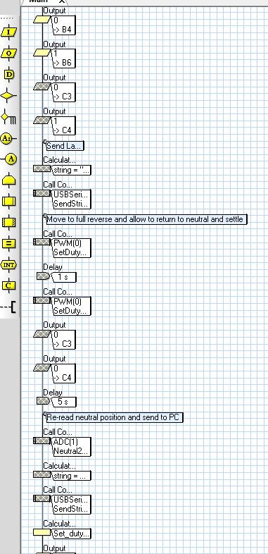
Here is the problem. The calibrated minimum Duty Cycle for 1 direction ends up too low (and possibly too high the other direction).

I have attached the Flowcode I used for this experiment.
Edit: added some comments to the flowchart
I have attached the Flowcode I used for this experiment.
Edit: added some comments to the flowchart
- Attachments
-
- Min_Duty_Cycle_Cal.fcf
- (27.39 KiB) Downloaded 284 times
-
GTF
- Posts: 170
- Joined: Sat Dec 10, 2011 7:21 pm
- Location: Canada
- Has thanked: 20 times
- Been thanked: 52 times
- Contact:
Re: ADC read problem
More odd behaviour......
If I disable the second read of the neutral position it is the first minimum duty cycle determination that does not work correctly. Although the targeted position change is reported, there was no change in voltage on the meter, no movement and no PWM applied.
In this case the disabled section of the flowchart does not occur until after the section that does not function correctly!
-
zadah
- Posts: 31
- Joined: Wed May 02, 2012 5:49 pm
- Has thanked: 3 times
- Been thanked: 7 times
- Contact:
Re: ADC read problem
Have you tried filtering capacitor on input pin of the PIC?
How about different potentiometer with lower resistance?
How about different potentiometer with lower resistance?
-
GTF
- Posts: 170
- Joined: Sat Dec 10, 2011 7:21 pm
- Location: Canada
- Has thanked: 20 times
- Been thanked: 52 times
- Contact:
Re: ADC read problem
zadah wrote:Have you tried filtering capacitor on input pin of the PIC?
How about different potentiometer with lower resistance?
There is a 470nf cap and a 100k pulldown on the circuit. The pot is already proven with other controllers/firmware.
I have also tried multiple samples/averaging with the same results. My impression is that the values being used in the calculations can be off by multiple times the theoretical ADC resolution. So for example, the current position can be determined to be on the opposite side of the stored neutral position than it actually is, requiring the use of a wider than acceptable deadzone.
The stored values appear to be consistent when read back multiple times, so perhaps the problem is inconsistency in the ADC conversion.
-
GTF
- Posts: 170
- Joined: Sat Dec 10, 2011 7:21 pm
- Location: Canada
- Has thanked: 20 times
- Been thanked: 52 times
- Contact:
Re: ADC read problem
Although further testing is required to confirm desired operation, it seems my CPU clock speed was low.