Page 1 of 1
PWM PIC18F47K40
Posted: Sat May 30, 2020 11:55 am
by jollybv
Hi Guys
I am trying to get the PWM to work it works in the test program below in simulation but will not work on the hardware any ideas
Re: PWM PIC18F47K40
Posted: Sat May 30, 2020 2:09 pm
by medelec35
Hi Brian,
First I would suggest to make sure FC7 is fully up to-date, if not already done so.
You can update will the files from
here.
I had an issue with PWM on 27K40 running FC8.
I posted a work around
here as it could also apply to FC7 as well with your target device?
Of course, don't forget to make sure the
one second flasher works.
I have moved topic to a more suitable place than user components.
Re: PWM PIC18F47K40
Posted: Sun May 31, 2020 10:21 am
by jollybv
Hi Martin
Thanks, I have tried all of the above suggestions but still can't get it to work, 1-second flasher working on RB0 So Pick working correctly, Have updated flowcode tried using Timer 4 still noting so not sure where to go from here.
Re: PWM PIC18F47K40
Posted: Mon Jun 01, 2020 4:47 pm
by howard123
Hi Brian
I have no idea if this is relevant but I noticed that the watchdog is on. Also could you try TMR2 and TMR4 with the PWM disabled. Set each timer to interrupt at a defined frequency and test on a pin that the frequency is correct.
Howard
Re: PWM PIC18F47K40
Posted: Tue Jun 02, 2020 7:51 am
by jollybv
Hi Howard
Thanks for the reply I have turned off the watchdog timer but that does not help. I'm not sure how to set the timer 2 and 4 to show me a predetermined frequancy could you please explain
Re: PWM PIC18F47K40
Posted: Tue Jun 02, 2020 11:56 am
by Benj
Maybe try enabling the associated timer interrupt using an interrupt icon. The interrupt macro could just be a blank macro. That might help get things moving and would help us to know where in the code to look for the problem.
Re: PWM PIC18F47K40
Posted: Tue Jun 02, 2020 12:23 pm
by jollybv
Hi Ben
I have tried to do that without any luck, but if I enable the disabled code in the TimerInt macro in the example program below then I get a frequency of 492Hz, this PWM refuses to work on any of the timers.
Re: PWM PIC18F47K40
Posted: Tue Jun 02, 2020 12:58 pm
by medelec35
jollybv wrote:then I get a frequency of 492Hz,
Did you set the timer 2 prescale and rollover as explained in the link I posted?
I had the same issue as you.
I could then at least control the PWM frequency.
Re: PWM PIC18F47K40
Posted: Tue Jun 02, 2020 2:31 pm
by jollybv
Hi Martin
I'm a bit lost now
The PWM will work at the correct frequency if Timer2 interrupt Prescale Rate is set to the required PWM Prescale.
Timer 2 interrupt Rollover Value is set to the required PWM period.
The timer 2 interrupt can be enabled, then disabled straight away.
I have set the rollover time of the
TMR2 Interrupt to 255 and the prescale Rate to 64 it is enabled then strait away disabled.
I have also set the
PWM Period Overflow to 255 and the Prescale To 64
I'm still not getting anything please see in the test program if I'm understanding you correctly.
Re: PWM PIC18F47K40
Posted: Tue Jun 02, 2020 2:50 pm
by medelec35
I have modified your flowchart so hopefully PWM will run at 4KHz
Re: PWM PIC18F47K40
Posted: Tue Jun 02, 2020 3:08 pm
by jollybv
Thanks, Martin but ist still does not work think there must be something wrong with the PWM component
Re: PWM PIC18F47K40
Posted: Tue Jun 02, 2020 3:32 pm
by medelec35
Hi Brian,
No problem.
jollybv wrote:think there must be something wrong with the PWM component
Yes, seems like it.
Was just trying to get it kick stated as will help Ben to fix it.
That's what happened with 18F27K40
Have you tried changing mapping for a different pin?
Also, can you set the duty to 15 rather than a variable.
Re: PWM PIC18F47K40
Posted: Tue Jun 02, 2020 3:40 pm
by jollybv
Hi yes have remapped with no success
and did set the duty cycle to 15 but alas no luck,
Re: PWM PIC18F47K40
Posted: Thu Jun 04, 2020 7:22 am
by jollybv
Hi Guys
As the PWM Component is not working and I'm waiting for Ben to have a look at it, does anyone know how I can make a PWM using a timer interrupt?
Re: PWM PIC18F47K40
Posted: Thu Jun 04, 2020 8:38 am
by medelec35
Hi Brian,
What PWM frequency is required?
With bit bang, best to have as lower frequency as possible.
Re: PWM PIC18F47K40
Posted: Thu Jun 04, 2020 9:48 am
by medelec35
I have had a go at fixing the PWM.
I have noticed form looking at the file I2C will require fixing as well.
Unable to verify if working, as not got PIC18F47K40 to test with.
Therefore, may or may nor work?
If 64 bit windows:
Can you place the attached file in C:\Program Files (x86)\Flowcode 7\FCD\PIC\
Or if 32bit windows:
C:\Program Files\Flowcode 7\FCD\PIC\
Best to keep a copy of the original file.
Re: PWM PIC18F47K40
Posted: Thu Jun 04, 2020 1:50 pm
by jollybv
Hi Martin
Sorry for responding so late been out the whole day, Thanks for your help I will give it a try and let you know
Re: PWM PIC18F47K40
Posted: Thu Jun 04, 2020 2:05 pm
by jollybv
Hi Martin
I have given it a try and it is now working Thanks so much

Re: PWM PIC18F47K40
Posted: Thu Jun 04, 2020 2:31 pm
by medelec35
jollybv wrote:I have given it a try and it is now working Thanks so much
,
Glad its working for you.
Thanks for the update.
At least you can carry on until an official fix from Matrix.
Ben has been on Holiday, so no doubt will have lots of catching up to do.
Re: PWM PIC18F47K40
Posted: Fri Jul 17, 2020 8:40 am
by jollybv
Hi Guys
Im not sure if this is still part of the problem with the A/D component not working correctly. On A0 I have a voltage of 0.182 which im trying to display on the LCD screen. I'm using (get analog voltage) and then converting it to a string then printing to screen but what it displays is 0.078 and sometimes flashes 0.182 it looks like it is not reading the correct voltage every time not sure if its me that is doing somthing wrong or there is a bug still in the PIC18F47K40.
I would like to get this resolved as soon as posible as i need to test this over the weekend
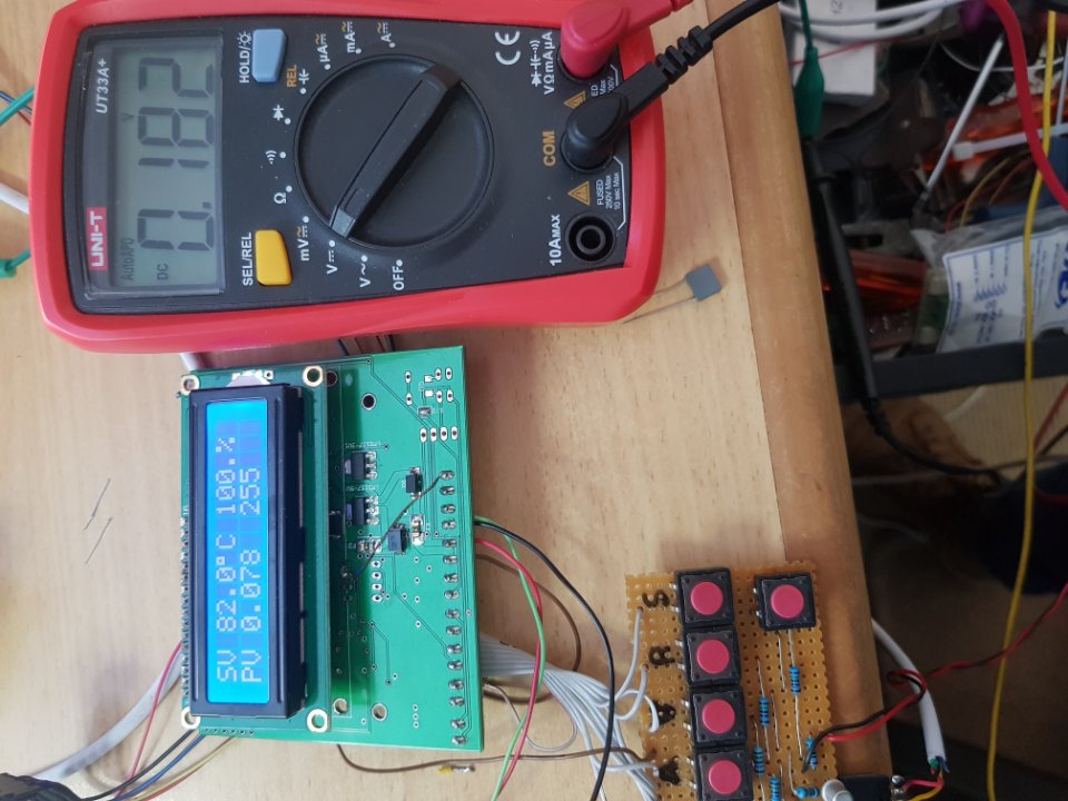
- Pic1.jpg (128.62 KiB) Viewed 9847 times
Re: PWM PIC18F47K40
Posted: Fri Jul 17, 2020 12:44 pm
by Benj
Maybe try a slower conversion speed and see if that helps, might be a touch too fast at the current clock speed, also do you have any noise present on the ADC pin, Maybe a decoupling capacitor to ground or a full R/C filter to help some noise rejection?
Re: PWM PIC18F47K40
Posted: Fri Jul 17, 2020 2:14 pm
by jollybv
Hi Ben
Thanks for your reply that seems to have solved the problem I set it to Focs / 128, now I need to get the PID side of things working (tried buying a PID controller but with this Vuires cant get much here in SA)