Page 1 of 2
Multi One Wire Example
Posted: Tue Jul 15, 2008 9:28 pm
by PINTO
Hi Benj,
I' working with the Multi One Wire Example and can't read more than 2 devices.
Pic 877a, 8Mhz, Delay 2, 4*DS18B20.
Please see the attached code. Were did I go wrong.
Regards
Pinto
Re: Multi One Wire Example
Posted: Thu Jul 24, 2008 9:39 am
by Eric
Hi,
I have the same problem: up to 2 devices are recognised, any additional device is not.
The function "GetDeviceCount" always returns 2 if more than 2 devices are connected.
5 X DS1820
PIC16F877A
8 Mhz
- snap055.jpg (27.6 KiB) Viewed 25657 times
Please advice.
Eric
Re: Multi One Wire Example
Posted: Thu Jul 24, 2008 1:43 pm
by PINTO
Hi Eric,
Thanks for sharing your info.
Are you using a simulator or the real devices on your design?
I used a simulator. But I don't think the problem is on the simulator because I loaded a similar software from another compiler and detected 10 devices complete with serial no's, temps and alarm status report.
I think that the problem could be on the timing rotines on the Component software.
I'm wainting for the MM support team to comment on the subject.
Regards
Pinto
Re: Multi One Wire Example
Posted: Thu Jul 24, 2008 3:02 pm
by Sean
Here is a new 1-Wire custom component with a possible fix for the scanbus() function, allowing more than two devices to be detected.
We are not currently able to test this component, but if anyone wants to give it a try we would be interested to know the results. A tested version should be available in the next few days.
Re: Multi One Wire Example
Posted: Thu Jul 24, 2008 11:28 pm
by Eric
Hi Sean,
For your information: I tried your new custom_code on the Multiple One wire example in the beta components page on my develloper board.
Attached were 5 DS1820 sensors in parallel with all the data lines pulled up to 5 volt with 4k7.
Unfortunatly the result is the same: 2 devices detected.

- snap025.jpg (9.84 KiB) Viewed 25417 times
I don't suspect the hardware because I compiled the same functionality with another compiler and there were all 5 sensors detected.
Regards,
Eric
Re: Multi One Wire Example
Posted: Fri Jul 25, 2008 9:59 am
by PINTO
Hi Sean,
Thanks for your info.
I've tried it as well and only detected 2 devices.
Thanks
Pinto
Re: Multi One Wire Example
Posted: Wed Jul 30, 2008 12:11 pm
by Benj
Hello
I have just tried the attached code with the Dallas DS1820 one wire sensors from Farnell code 972-4761.
The code is correctly detecting up to 4 devices (thats all I have) and then displaying the temperature of the devices.
Re: Multi One Wire Example
Posted: Thu Jul 31, 2008 10:35 am
by Eric
Hi Benj,
I tried your code, but now the result is always ERR255. Meaning 0 devices detected whatever how many devices are connected.
My devices are connected to portA, therefore I changed the customcode properties to portA.
But to eliminate errors, I also tried it on portB like you did, but the result is the same.
Please advice.
Regards,
Eric
Re: Multi One Wire Example
Posted: Thu Jul 31, 2008 11:39 am
by Benj
Hello
I was receiving the Err255 message when trying to use pin RA0, Therefore I moved to Pin RB0 and the one wire bus started working.
I have just retested the code using parasitic and non parasitic power and have been able to detect all 4 of my devices.
Please could you provide a little more info regarding your setup:
Processor - Eg 16F877A
Clock Speed - Eg 19.6608MHz
One Wire Pin - Eg RB0
Exact product code of one wire sensor - Eg DS1820
Data pull up resistance - Eg 4.7K
Parasitic / Normal power mode
Anything else you can think of
Also would you mind attaching your program to the forum post so I can use your exact hardware setup and your program to do the testing.
Re: Multi One Wire Example
Posted: Tue Aug 05, 2008 7:19 pm
by PINTO
Hi Ben,
If you want to use port A you should turn off the ADC and make the portA as a digital I/O.
ADCON1 = $07 'Turn PORTA as Digital IO.
ADCON0 = 0 'Turn off all A/D's
I'm still battling, trying to detect more than 3 devices.
One thing I noticed is that I don't see where you save the information from the OO's into EEprom?
Regards
Pinto
Re: Multi One Wire Example
Posted: Tue Aug 05, 2008 7:56 pm
by Eric
Hello Benj,
My hardware is a developper board from Mikroelektronika:
UNI-DS3, see
http://www.mikroe.com/en/tools/unids3/
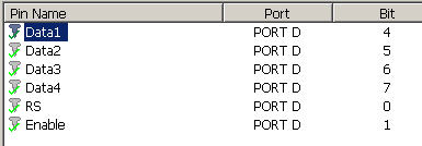
This board works fine for me. The only changes I have to make is to connect the lcd to portD instead of PortB.
- snap033.jpg (10.82 KiB) Viewed 25140 times
My setup is this:
Processor: 16F877A
Clock Speed: 8.000000 MHz
One Wire Pin: RA0
One wire sensor: DS1820
Normal power mode
5 sensors in parallel with all datalines connected to +5 volt via 1 resistor of 4k7
Config word: 0x2007,0x3f3a
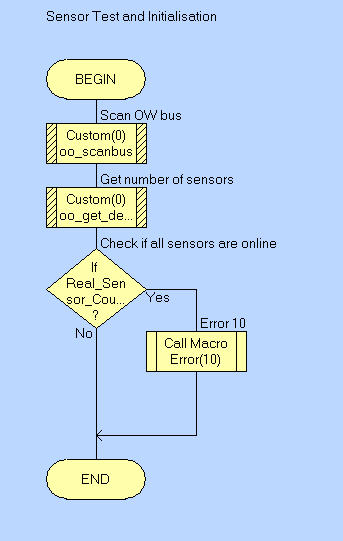
In my program I use this code to detect the number of sensors:
//Macro implementations
void FCM_Sensor_Init(char FCL_REQUIRED)
{
//Sensor Test and Initialisation
//Scan OW bus
//Call Component Macro: Custom(0)::oo_scanbus
FCD_Custom0_oo_scanbus();
//Get number of sensors
//Call Component Macro: Real_Sensor_Count=Custom(0)::oo_get_devicecount
FCV_REAL_SENSOR_COUNT = FCD_Custom0_oo_get_devicecount();
//Check if all sensors are online
//Decision: Real_Sensor_Count <> Required_Sensor_Count?
if (FCV_REAL_SENSOR_COUNT != FCV_REQUIRED_SENSOR_COUNT)
{
//Error 10
//Call Macro: Error(10)
FCM_Error(10);
}
}
I call the macro with the parameter "number of installed and required sensors" and compare the result with the " real found number of sensors".
REAL_SENSOR_COUNT is 0 if no sensor is detected, 1 if 1 sensor is present and 2 if 2 sensors are detected. From than on, the return is always 2 whatever sensors are added. If I change the customcode properties to portb and trisb and connect the sensors to portB, this still works.
If I use your code OneWire.zip from your last message on Wed Jul 30, 2008 11:11 am, I always get Error255 as return, whatever I connect it to portA or portB
I hope this helps.
Thanks for trying.
Eric
Re: Multi One Wire Example
Posted: Mon Sep 01, 2008 7:13 am
by Mikat
At last i tested the code too..
The results was that the code works only the portb pin 0,i tried other pins on port b,but no success,and same results on port C,but i didnt test on pin 0 on other ports..
Guys,do you have any idea why?
The code dont report more than 2 devices...
The temp calc is probably on the ds18b20 device,but thats not problem,the only difference is the temp calc...
The devices what i use is ds1820,direct from maxim...
Re: Multi One Wire Example
Posted: Sat Jan 10, 2009 8:13 am
by JCMB
J am french, sorry for my english.
After a lot of test, j found bugs in NEXT code.
Attached OneWireMultiDS.zip with: Custom_Code_1W_get_IDByte.c, that is custom_code.c modified with one macro added.
1WMultiDS.fcf for test.
Re: Multi One Wire Example
Posted: Mon Jan 12, 2009 5:44 pm
by Benj
Hello JCMB
Please can I ask which bug you found and what you did to fix the problem. Does this relate to the multiple device detection problem. Also what does the function you added do to get around the problem.
Re: Multi One Wire Example
Posted: Tue Jan 13, 2009 2:45 pm
by JCMB
Hello Ben.
J used to read temps 8 x DS18 (5 x DS18S20 and 3 x DS18B20).
Only 2 to 4 DS18 were detected.It depend of wich DS18 were connected.
So j ad a macro called 1W_get_IDByte, 2 param (Num of the device and num of the byte to be return).
It return the byte of the lasered rom code stored in DevID.
J found that the pb was in macro oo_get_next_id()
"if (id[byte_index] && (1 << bit_index))".
This test always return 1 (id[byte_index] true, (1 << bit_index) true).
So j add a variable (char) bit_test and replace "if (id[byte_index] && (1 << bit_index))" by
bit_test = id[byte_index] >> bit_index;
if (bit_test & 0x01)
J also add 2 var : char lz_selected = 0; (Last zero selected)
char go_on = 0;
// use previous value
bit_test = id[byte_index] >> bit_index; //added JCMB 10/01/09
if (bit_test & 0x01)
{
val0 = 1;
}
else
{
val0 = 0;
lz_selected = counter; //added JCMB 10/01/09
go_on = 1; //added JCMB 10/01/09
}
After the end of the loop "for (byte_index = 0; byte_index < 8; byte_index++)" j add
if ((new_conflict == 0) && go_on) // (new_conflict == 0) AND go_on must be true
{
new_conflict = 1;
conflict = lz_selected ;
}
Now J detect 8 DS18, use the macro 1W_get_IDByte to read the FAMILY CODE, and so do automatic temps convert.
Re: Multi One Wire Example
Posted: Tue Jan 13, 2009 3:00 pm
by Benj
Hi
Ok thats great thanks for confirming the problem and providing the workaround. I will give it a go here and try and incorperate what you have done into the functionality of the one wire component.
Re: Multi One Wire Example
Posted: Sat Feb 14, 2009 8:12 am
by JCMB
2 errors corrected in 1WMultiDS.fcf
Switch D0 erased (No use).
In macro TempToStr, bit 0 does'nt add 625 to rest.
Re: Multi One Wire Example
Posted: Sun Feb 15, 2009 6:10 pm
by JCMB
Sorry J found an other bug in my 1WMultiDS.fcf.
In macro TempToStr, for DS18B20 and negative temperature, the resulte was
1 Β°C too low.
Re: Multi One Wire Example
Posted: Mon Feb 16, 2009 12:05 pm
by Benj
Great thanks for the updates. I will add your file to the main one wire example download if that is ok with you.
Re: Multi One Wire Example
Posted: Tue Feb 17, 2009 4:00 pm
by JCMB
Ok to add the file to the main one wire example download.
J made an other change in the macro TempToStr.
In the Custom_Code.c J rename CUSTOM_Dummy_Function() to ONEW_Dummy_Function() because of a conflict with other component.
Re: Multi One Wire Example
Posted: Tue Mar 15, 2011 8:06 am
by technoboy
how to read 64 bit rom code using 1 wire component oo_read_device ??
there is count variable and return byte.......how to store all 8 byte ?
plz help me......
Re: Multi One Wire Example
Posted: Tue Mar 15, 2011 10:49 am
by Benj
Hello,
This is from the one wire component help file.
oo_BusReset()
Resets all of the devices connected to the One Wire bus. Returns a 0 if succsessful and a 1 if no devices are present or reset.
oo_GetPadByte(byte index)
Returns a byte from the last read scratchpad at position index. The index byte can go from 0 - 8 to reference the 9 individual scratchpad bytes.
oo_Tx_Byte(byte data)
Transmits the byte data over the one wire bus.
oo_Rx_Byte()
Returns a byte from the one wire bus.
oo_ScanBus()
Scans the one wire bus for devices. Inserts the number of devices into a variable called num_devices. See Get_DeviceCount function. Returns a 0 if sucsessful and an error code if there was a problem.
oo_Get_DeviceCount()
Returns the number of devices connected to the one wire bus. Must be run after the ScanBus function.
oo_ReadDevice(byte Count)
Reads one of the devices detected using the ScanBus function. Loads the remote scratchpad from the device into the local buffer. See the GetPadByte function.
DS1820_Start_Conversion()
Specific to the DS1820 and DS18B20 devices. This function resets all of the one wire devices on the bus and then skips the ROM address and starts a temperature conversion. Returns a one if the devices time out without finishing the conversion.
DS1820_Read_Scratchpad()
Specific to the DS1820 and DS18B20 devices. This function must only be called if there is only one device on the bus as it skips the ROM address. If there is more then one device on the bus then the ScanBus and ReadDevice functions must be used. Loads the remote scratchpad from the device into the local buffer. See the GetPadByte function.
DS1820_Get_Temp()
Specific to the DS1820 and DS18B20 devices. This function returns the integer value representing the temperature which is stored in the local buffer. The value returned represents the temperature in levels of 0.0625 degrees Celcius. Therefore if you get a value of 400 then the temperature is equivalent to 25 degrees C. An easy way to convert this into a readable value is to either devide by 16 and have an integer number or use the 32 bit floating point plugin and devide by 16 to get the temperature to within 0.0625 of a degree.
Re: Multi One Wire Example
Posted: Mon Mar 21, 2011 5:13 am
by technoboy
Thanks benj,
I am using ds1990a.......... i just want to read 64 bit rom code and have to compare with already stored code in pic.
So which function to use ? is it oo_readdevice & oo_getpadbyte functions ?
Regards,
tanveer
Re: Multi One Wire Example
Posted: Mon Mar 21, 2011 11:22 am
by Benj
Hello,
scan bus - scan bus for devices.
read device - reads scratchpad from a detected device.
get pad byte - reads back a byte from the scratchpad.
Re: Multi One Wire Example
Posted: Tue Mar 22, 2011 11:25 am
by technoboy
hello Ben,
Thanks for the reply

...... I tried but i am not able to read romcode of ds1990a

. I am using pic16f877a and a single 1wire device (ds1990a) . Can you please show me a flowcode example file to read romcode and display it in lcd ?
Thank you