Page 1 of 1
Variable Frequency Generator 500Hz to 5KHz (100 Hz Steps)
Posted: Wed May 25, 2011 5:46 pm
by medelec35
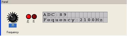
I have developed a simple Square wave frequency generator for Flowcode V4, which covers 500Hz to 5KHz in 100Hz steps with Frequency displayed on LCD.
Also displayed is byte value of POT connected to RA0.
I have used a 16F88 configured for 8MHz internal oscillator. This cuts down component count.
You can use output's RA1 to ground which produces 5V Peak, or use RA1 and RA2 and this produces 10V Peak since RA1 o/p is complement to RA2.
I have tested O/P with a frequency counter and frequency on my setup is very close to displayed frequency.
If you have a piezo transducer with unknown resonant frequency, just connect between RA1 and RA2.
Adjust POT to vary frequency through whole range. When Volume is at its loudest, then you have found the correct working frequency.
If you find transducer too loud then connect between RA1 and GND.
When compiling code, You will see the following warning:
Code: Select all
Freq Gen1.c(1092): WARNING: This interrupt has previously been enabled, so the macro <Timer0_tick> may never get called.
Freq Gen1.c(1105): WARNING: This interrupt has previously been enabled, so the macro <Timer0_tick> may never get called.
Freq Gen1.c(1118): WARNING: This interrupt has previously been enabled, so the macro <Timer0_tick> may never get called.
This is normal, and is only intend if interrupt is not disabled prior to re-enabling.
Since within code, interrupt is disabled first, message does not apply.
- Freq Gen1.JPG (10.36 KiB) Viewed 28080 times
Martin
Re: Variable Frequency Generator 500Hz to 5KHz
Posted: Wed May 25, 2011 6:06 pm
by JohnCrow
Nice little project, will have to try it on hardware when I have a bit of time
Re: Variable Frequency Generator 500Hz to 5KHz
Posted: Wed May 25, 2011 6:39 pm
by Spanish_dude
Hi,
Nice project

.
I didn't know about the RA1 and RA2 output pins.
You could have a much lower frequency by using a software frequency divider.
Re: Variable Frequency Generator 500Hz to 5KHz
Posted: Wed May 25, 2011 7:39 pm
by medelec35
Thanks John & Nicolas.
The Idea for generator was to determine resonance frequency for Piezo transducer.
since the normal range is 1KHz to 5KHz, I thought I would use that as a basis.
As for reducing frequency. I can do that by just placing a If count is less than a variable then port A1:A2 = 0 etc.
Spanish_dude wrote:I didn't know about the RA1 and RA2 output pins.
That's only the way the software has been designed to work, it does not normally work this way.
IMPORTANT!
frequency generator will only work with 8MHz OSC.
Using any other value will mean the frequency generated will be well out of tolerance.
Martin
Re: Variable Frequency Generator 500Hz to 5KHz (100Hz Steps)
Posted: Wed May 25, 2011 11:36 pm
by medelec35
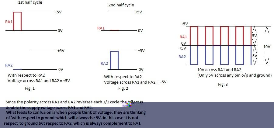
For people who are interested, I was asked in a pm how the 10V is generated:
To generate 10V pk to pk with a 5V supply.
here is a diagram to help illustrate principle
On first 1/2 cycle: Simultaneously the software drives RA1 to 5V and RA2 to 0V
on the 2nd 1/2 cycle: Simultaneously the software drives RA1 to 0V and RA2 to 5V, So RA1 and RA2 are complementary.
So if you connect one end of piezo transducer to RA1 and the other end to RA2, the transducers sees 10V pk to pk instead of 5V.
- 10V pk to pk.jpg (46.45 KiB) Viewed 28031 times
Hope this helps.
Martin
Re: Variable Frequency Generator 500Hz to 5KHz (100 Hz Steps
Posted: Sat Apr 07, 2012 10:05 am
by Xavier
A very interesting project I think of using it on my PI detectors for experimental per posses but I would need it to go from 50Hz to 200Hz. Now if some body would tell me how to send a thanks I'd be most appreciative.

All the best
Xavier
Re: Variable Frequency Generator 500Hz to 5KHz (100 Hz Steps
Posted: Sat Apr 07, 2012 10:15 am
by Xavier
OK found the thanks he he it was on the other page and not on the reply page
Regards Xavier
Re: Variable Frequency Generator 500Hz to 5KHz (100 Hz Steps
Posted: Sun Jul 22, 2012 6:12 pm
by Creative25
Hi to all.
I just wonder.
Does this suggest the sounder has to be connected directly. (Without transistors.)
Do you then connect it with two resistors?
What value would u use for a TDK PS1740P02E piezo sounder?
Best Regards:
Uli
Re: Variable Frequency Generator 500Hz to 5KHz (100 Hz Steps
Posted: Wed Jul 25, 2012 3:10 pm
by Enamul
Hi,
You should use some driving circuit which can be like the attachment...
Does this suggest the sounder has to be connected directly. (Without transistors.)
Do you then connect it with two resistors?
What value would u use for a TDK PS1740P02E piezo sounder?
To have proper driving current..use 5 v as supply..
Enamul
Re: Variable Frequency Generator 500Hz to 5KHz (100 Hz Steps
Posted: Wed Jul 25, 2012 5:30 pm
by medelec35
I just connected piezo element directly between RA1 and RA2 and it was very loud.
Had to cover ear if got to near.
This was due to hitting resonant frequency of piezo element.
Did not use any resistors or transistors.
Just a 5V supply.
That gave 10V pk to pk
With Enamul's circuit, it will be even louder at 24V pk to pk
I'm not sure about the 1K x 2 being there. Won't it turn transistors into emitter followers, so emitters ties to be 0.7V lower than base i.e approx 4.3V in the case of NPN.
I could be wrong as not testing that theory.
Martin
Edit: corrected spelling mistakes with mittens off this time

Re: Variable Frequency Generator 500Hz to 5KHz (100 Hz Steps
Posted: Wed Jul 25, 2012 6:44 pm
by Enamul
Hi Martin,
Thanks for the confusion. But I have mentioned him to use 5v supply..for 10v p-p.
With Enamul circuit, it will be even louder at 24V pk to pk
I'm nut sure about the 1K x 2 being there. Won't it turn transistors into emitter followers, so E ties to be 0.7V lower than base i.e approx 4.3V
I could be wrong as not testing that theory.
I have modified the circuit to avoid any confusion..now current is limited and he can change p-p swing voltage by changing supply voltage.
Enamul
Re: Variable Frequency Generator 500Hz to 5KHz (100 Hz Steps)
Posted: Fri May 08, 2020 7:17 pm
by siliconchip
hi martin
ive come across this post you made several years ago, would you be able to explain the math in the calculation box,i wouldn't mind adapting this from 1 - 2000 Hz if possible ive had a play but do not understand the calculations,cheers
bob
Re: Variable Frequency Generator 500Hz to 5KHz (100 Hz Steps)
Posted: Sat May 09, 2020 12:32 am
by medelec35
Hi Bob,
It will not be easy to change the upper and lower rage get a low frequency without redesigning from scratch .
What I did was workout a formula that converted 0 - 255 to 500 to 5000
I.e. ADC * 9 / 50 * 100 + 500.
The calculation was spit up so we have byte only for the first part i.e ADC * 9 /50 = 0 to 45
That was used to enable different values of timer 0 interrupt.
Then the rest of the calculation together with the first part resulted in the 500 to 5000 required for the LCD.
Re: Variable Frequency Generator 500Hz to 5KHz (100 Hz Steps)
Posted: Sat May 09, 2020 11:15 am
by siliconchip
Hi martin
Thanks for the reply in the calculation where did the figure 9 and 50 come from

Bob
Re: Variable Frequency Generator 500Hz to 5KHz (100 Hz Steps)
Posted: Sat May 09, 2020 4:23 pm
by medelec35
It was long time ago indeed

I used the Formula Generator I posted
here.
I wanted a range between 0 and 45 when ADC is between 0 and 255, so I entered the following :
- FG1.png
- (36.55 KiB) Downloaded 570 times
However need another step as wanted the LCD to display from 500 to 5000.
So for step 2, entered the following :
- FG2.png
- (40.31 KiB) Downloaded 570 times
Can ignore the /1 hence
Re: Variable Frequency Generator 500Hz to 5KHz (100 Hz Steps)
Posted: Sat May 09, 2020 6:40 pm
by siliconchip
hi martin
once again thanks yes i think you first posted this 9 years ago, could i use a similar formula to run from 1Hz upwards
bob
Re: Variable Frequency Generator 500Hz to 5KHz (100 Hz Steps)
Posted: Sat May 09, 2020 7:07 pm
by medelec35
Hi Bob,
Not with the flowchart I posted as its based on timer interrupt.
Like stated earlier, you will need to start again.
There may be an easier way do do this?
What target device and clock frequency are you thinking of using?
Re: Variable Frequency Generator 500Hz to 5KHz (100 Hz Steps)
Posted: Sat May 09, 2020 7:11 pm
by siliconchip
hi martin
using your formula generator ive added a flowchart to try and hit my 1Hz upwards, all ive done is run it at 8MHz no config done yet, can you confirm i am on the right track please ?? target device probably a 16f1825 although for this ive quickly used a 16f88
bob
Re: Variable Frequency Generator 500Hz to 5KHz (100 Hz Steps)
Posted: Mon May 11, 2020 8:13 pm
by medelec35
Hi Bob,
What resolution are you are you after?
What you need to take in account is
Code: Select all
Frequency of square wave = Interrupt_Freq /((Timer_Tick_Value+1)*2)
.
Therefore interrupt frequency needs to be as high as possible.
As timer_Tick increased the resolution goes from course to fine in a logarithmic way.
If possible, need to use a much better microcontroller to clock frequency can be much higher than 8MHz.
To use a similar method to the original version, A look up table will need to be developed for every single frequency.
The new method just requires a calculation to produce the desired frequency.
Re: Variable Frequency Generator 500Hz to 5KHz (100 Hz Steps)
Posted: Mon May 11, 2020 11:11 pm
by medelec35
Hi Bob,
Attached is a frequency generator that goes from 7 Hz to 2KHz
You will need a microcontroller that goes up to at least 32MHz for it to work.
It works by calculating the timer tick required from the formula I have posted on the above post.
This greatly simplifies the flowchart compared with the 500 to 5KHz flowchart as lookup table is not required.
Re: Variable Frequency Generator 500Hz to 5KHz (100 Hz Steps)
Posted: Tue May 12, 2020 2:43 pm
by siliconchip
hi martin,
thanks for taking the time to work this out, i need a better understanding on how interrupts work along with the calculation side of things i have been playing around with timings to try and find an answer but what you have provided hits the nail on the head i need to dissect this and get my head around it,
bob
Re: Variable Frequency Generator 500Hz to 5KHz (100 Hz Steps)
Posted: Tue May 12, 2020 4:46 pm
by medelec35
You're welcome Bob.
If you get stuck then let me know.
Re: Variable Frequency Generator 500Hz to 5KHz (100 Hz Steps)
Posted: Thu May 14, 2020 5:47 pm
by siliconchip
thanks martin
bob
Re: Variable Frequency Generator 500Hz to 5KHz (100 Hz Steps)
Posted: Tue May 26, 2020 2:56 am
by medelec35
Hi Bob,
You're welcome.
There is now a better to change from one set of values to another.
Its using a new
Map Function component
The results will be more accurate then using a formula generator