|
Electronic circuits and components
Fundamentals
Passive Components
Semiconductors Passive Circuits
Active Circuits
Parts Gallery |
Simple Power Supply<^< Worksheet: Reservoir and Smoothing Circuit | Course Index | Worksheet: Simple Power Supply >^> 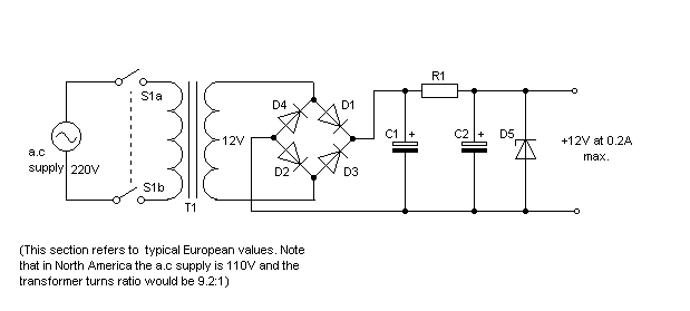 The circuit diagram shows a complete power supply in which the mains is isolated by the double-pole single-throw (DPST) on/off switch, S1. T1 then acts as a step-down transformer (turns ratio 18.3:1) whilst D1-D4 form a full-wave bridge rectifier. C1 is the reservoir capacitor whilst R1 and C2 act jointly as a low-pass smoothing filter. Finally, Zener diode, D5, acts as a voltage regulator maintaining the output voltage at a reasonably constant 12V. In determining the component values for the circuit, it is important to note that the reservoir capacitor, C1, will charge to the secondary voltage of T1 less the forward voltage drops associated with two conducting diodes in the bridge configuration. In the arrangement shown, the voltage drop across C1 will thus be approximately (12 x 1.414V) - (2 x 0.65V) or about 15.7V (you should recall that the '12V' secondary voltage rating is quoted as an 'r.m.s. voltage' and this needs to be converted to a peak voltage by multiplying by 1.414). If the Zener diode is rated at 12V, the voltage drop across R1 will be approximately (15.7V - 12V) or 3.7V. Typical component values are; D1-D4 = 1N4001, D5 = 1N5349, R1 = 15Ω 2.5W, C1 = C2 = 2,200μF. <^< Worksheet: Reservoir and Smoothing Circuit | Course index | Worksheet: Simple Power Supply >^> |